MCP2150DM Microchip Technology, MCP2150DM Datasheet - Page 12
MCP2150DM
Manufacturer Part Number
MCP2150DM
Description
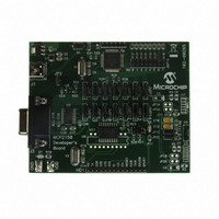
BOARD DEMO FOR MCP2150
Manufacturer
Microchip Technology
Specifications of MCP2150DM
Main Purpose
Interface, IrDA
Embedded
Yes, MCU, 8-Bit
Utilized Ic / Part
MCP2150
Primary Attributes
IrDA Controller with PIC18F MCU
Secondary Attributes
USB Interface
Processor To Be Evaluated
MCP2150, MCP2155
Processor Series
MCP215x
Interface Type
USB
Lead Free Status / RoHS Status
Lead free / RoHS Compliant
Lead Free Status / RoHS Status
Lead free / RoHS Compliant, Lead free / RoHS Compliant


MCP2150
2.9.1.2
The MCP2150 supports the IrLAP protocol. The IrLAP
protocol provides:
• Management of communication processes on the
• A device-to-device connection for the reliable,
• Device discover procedures.
• Hidden node handling.
Figure 2-7
IrDA protocols. The bottom layer is the Physical layer,
IrPHY. This is the part that converts the serial data to
and from pulses of IR light. IR transceivers can’t trans-
mit and receive at the same time. The receiver has to
wait for the transmitter to finish sending. This is some-
times referred to as a “Half-Duplex” connection. The IR
Link Access Protocol (IrLAP) provides the structure for
packets (or “frames”) of data to emulate data that would
normally be free to stream back and forth.
FIGURE 2-7:
DS21655B-page 12
link between devices.
ordered transfer of data.
Host O.S. or Application
identifies the key parts and hierarchy of the
IrLAP
IrLMP – IAS
IrCOMM
IrPHY
IrLAP
IRDA STANDARD
PROTOCOL LAYERS
IR pulses
transmitted
and
received
Protocols
resident in
MCP2150
Preliminary
Figure 2-8
The frame is proceeded by some number of Beginning
of Frame characters (BOFs). The value of the BOF is
generally 0xC0, but 0xFF may be used if the last BOF
character is a 0xC0. The purpose of multiple BOFs is to
give the other station some warning that a frame is
coming.
The IrLAP frame begins with an address byte (“A”
field), then a control byte (“C” field). The control byte is
used to differentiate between different types of frames
and is also used to count frames. Frames can carry sta-
tus, data or commands. The IrLAP protocol has a com-
mand syntax of it’s own. These commands are part of
the control byte. Lastly, IrLAP frames carry data. This
data is the information (or “I”) field. The integrity of the
frame is ensured with a 16-bit CRC, referred to as the
Frame Check Sequence (FCS). The 16-bit CRC value
is transmitted LSB first. The end of the frame is marked
with an EOF character, which is always a 0xC1. The
frame structure described here is used for all versions
of IrDA protocols used for serial wire replacement for
speeds up to 115.2 kbaud.
FIGURE 2-8:
In addition to defining the frame structure, IrLAP pro-
vides the “housekeeping” functions of opening, closing
and maintaining connections. The critical parameters
that determine the performance of the link are part of
this function. These parameters control how many
BOFs are used, identify the speed of the link, how fast
either party may change from receiving to transmitting,
etc. IrLAP has the responsibility of negotiating these
parameters to the highest common set so that both
sides can communicate as quickly, and as reliably, as
possible.
Note 1: Another IrDA standard that is entering
X BOFs BOF A C
(1+N) of C0h payload
2: IrDA communication standards faster
shows how the IrLAP frame is organized.
general usage is IR Object Exchange
(IrOBEX). This standard is not used for
serial connection emulation.
than 115.2 kbaud use a different CRC
method and physical layer.
IRLAP FRAME
2002 Microchip Technology Inc.
I
bytes C1h
FCS
2
EOF
Related parts for MCP2150DM
Image
Part Number
Description
Manufacturer
Datasheet
Request
R

Part Number:
Description:
Manufacturer:
Microchip Technology Inc.
Datasheet:
Part Number:
Description:
Manufacturer:
Microchip Technology Inc.
Datasheet:
Part Number:
Description:
Manufacturer:
Microchip Technology Inc.
Datasheet:
Part Number:
Description:
Manufacturer:
Microchip Technology Inc.
Datasheet:
Part Number:
Description:
Manufacturer:
Microchip Technology Inc.
Datasheet:
Part Number:
Description:
Manufacturer:
Microchip Technology Inc.
Datasheet:
Part Number:
Description:
Manufacturer:
Microchip Technology Inc.
Datasheet:
Part Number:
Description:
Manufacturer:
Microchip Technology Inc.
Datasheet: