MCP3905RD-PM1 Microchip Technology, MCP3905RD-PM1 Datasheet - Page 13
MCP3905RD-PM1
Manufacturer Part Number
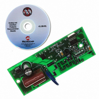
MCP3905RD-PM1
Description
REFERENCE DESIGN FOR MCP3905
Manufacturer
Microchip Technology
Specifications of MCP3905RD-PM1
Main Purpose
Power Management, Energy/Power Meter
Embedded
No
Utilized Ic / Part
MCP3905/6
Primary Attributes
1-Phase, 220 VAC, In Case, With Mechanical Counter
Secondary Attributes
On Board Transformerless AC/DC 5V Supply
Silicon Manufacturer
Microchip
Silicon Core Number
MCP3905A,MCP3906A
Kit Application Type
Power Management
Application Sub Type
Energy Meter
Kit Contents
Design Guides
Lead Free Status / RoHS Status
Lead free / RoHS Compliant
Available stocks
Company
Part Number
Manufacturer
Quantity
Price
Company:

Part Number:
MCP3905RD-PM1
Manufacturer:
MICROCHIP
Quantity:
12 000


2.4
© 2009 Microchip Technology Inc.
ENERGY METER REFERENCE DESIGN OVERVIEW
This reference design can be used as either a stand-alone mechanical counter energy
meter, or as the analog front-end design in advanced microcontroller-based meter
designs.
The AFE design limits the overall meter accuracy. A low noise, proven AFE circuit and
layout is still required for a high-accuracy meter. For both meter types, the current
sense input, voltage sense input, calibration scheme, jumper selection and power
supply design blocks described here should apply.
This reference design keeps all of the major components on the back-side of the PCB.
This minimizes any ill effects from the environment in the situation that a meter case
experiences failure. Only the necessary components for calibration, jumper selection
and external connections are placed on the front-side of the board. Keeping the larger
DC power supply components on the back-side of the board is also necessary for
installation in some meter cases with PCB standoffs.
The major components on the front-side of the MCP3905A/06A Energy Meter Refer-
ence Design are listed here and described in Section 2.5 “Front-Side Of PCB
Detailed Description”.
1. Shunts for Gain, FC and HPF selection (J11-J15).
2. Calibration jumpers (J1-J10).
3. Output connections for mechanical counter and calibration (JP5-JP7).
4. Input connection from the current-sensing element (JP1,JP2).
5. Input connection from voltage or phase line and ground reference point
6. The analog ground plane, power supply ground plane, moat.
The major components on the back-side of the MCP3905A/06A Energy Meter
Reference Design are listed here and described in Section 2.6 “Back Side Of PCB
Detailed Description”.
1. MCP3905A (U1).
2. DC Power Supply (C17, C16, U2, C18, etc.).
3. Metal Oxide Varistor (MOV1).
4. Optical isolator for PIC
These blocks, and their functionality, will be briefly described in the following two
sections. For more detailed information regarding design decisions and approaches to
IEC1036 compliance, refer to AN994, “IEC Compliant Active Energy Meter Design
Using The MCP3905A/06A” (DS00994). For a more detailed circuit schematic, refer to
Appendix A. “Schematics and Layouts” and Appendix B. “Bill Of Materials
(BOM)”.
(JP3,JP4).
®
Microcontroller Unit (MCU) or calibration (U3).
Installation and Operation
DS51565B-page 9
Related parts for MCP3905RD-PM1
Image
Part Number
Description
Manufacturer
Datasheet
Request
R

Part Number:
Description:
IC ENERGY METER 24-SSOP
Manufacturer:
Microchip Technology
Datasheet:

Part Number:
Description:
Energy-Metering ICs with Active (Real) Power Pulse Output
Manufacturer:
Microchip Technology
Part Number:
Description:
(MCP3905 / MCP3906) Energy-Metering ICs
Manufacturer:
Microchip Technology
Datasheet:

Part Number:
Description:
Manufacturer:
Microchip Technology Inc.
Datasheet:
Part Number:
Description:
Manufacturer:
Microchip Technology Inc.
Datasheet:
Part Number:
Description:
Manufacturer:
Microchip Technology Inc.
Datasheet:
Part Number:
Description:
Manufacturer:
Microchip Technology Inc.
Datasheet:
Part Number:
Description:
Manufacturer:
Microchip Technology Inc.
Datasheet:
Part Number:
Description:
Manufacturer:
Microchip Technology Inc.
Datasheet:
Part Number:
Description:
Manufacturer:
Microchip Technology Inc.
Datasheet: