MCP73831EV Microchip Technology, MCP73831EV Datasheet - Page 12
MCP73831EV
Manufacturer Part Number
MCP73831EV
Description
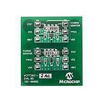
BOARD DEMO FOR MCP73831
Manufacturer
Microchip Technology
Type
Battery Managementr
Specifications of MCP73831EV
Main Purpose
Power Management, Battery Charger
Utilized Ic / Part
MCP73831
Product
Power Management Modules
Kit Contents
2x MCP73831 Evaluation Boards, Users Guide, Data Sheet
Features
Automatic Charge Termination, Charge Current Monitor, Preconditioning Of Deeply Depleted Cells
Svhc
No SVHC (15-Dec-2010)
Rohs Compliant
Yes
For Use With/related Products
MCP73831
Lead Free Status / RoHS Status
Contains lead / RoHS non-compliant
Secondary Attributes
-
Embedded
-
Primary Attributes
-
Lead Free Status / Rohs Status
Lead free / RoHS Compliant


2.3
DS51596A-page 8
GETTING STARTED
The MCP73831 Evaluation Boards are fully assembled and tested for charging
single-cell, Li-Ion/Li-Polymer battery packs. The boards provide the appropriate charge
algorithm for simple, stand-alone operation.
The boards require the use of an external input voltage source (5V ±10%,
recommended) and external load (battery pack or simulated battery load).
2.3.1
2.3.1.1
1. Apply the input voltage source to the appropriate circuit for evaluation. The input
2. Connect the positive side of the input source (+) to V
FIGURE 2-1:
2.3.1.2
1. To apply a load to a MCP73831 Evaluation Board, the positive side of the load
2. For the MCP73831-2AC board, the charge management controller will only
Battery Pack or
Simulated
Battery Load
voltage source should be limited to the 0V to +6V range. For normal operation,
the input voltage should be between +4.5V and +6V. The input voltage must not
exceed an absolute maximum of +7V.
evaluated. Connect the negative or return side of the input source (-) to V
the circuit being evaluated. Refer to Figure 2-1.
(B+) should be connected to V
return side of the load (B-) should be connected to V
uated. Care should be taken when using electronic loads or ground referenced
loads.
provide 10% of the programmed fast charge current if the battery terminal
voltage (V
will not work for preconditioning and fast charge currents. The best way to
evaluate the charge management circuit is to use a single-cell Li-Ion battery
pack, or the recommended simulated battery load. Refer to Figure 2-2.
Power Input and Output Connections
POWERING A MCP73831 EVALUATION BOARD
APPLYING THE LOAD TO A MCP73831 EVALUATION BOARD
+
_
BAT
) is less than 2.8V with respect to V
Setup Configuration Diagram.
BAT
of the circuit being evaluated. The negative or
SS
. Using a purely resistive load
SS
DD
© 2005 Microchip Technology Inc.
of the circuit being eval-
of the circuit being
_
+
Input
Power Supply
5.2V
SS
of
Related parts for MCP73831EV
Image
Part Number
Description
Manufacturer
Datasheet
Request
R

Part Number:
Description:
Manufacturer:
Microchip Technology Inc.
Datasheet:
Part Number:
Description:
Manufacturer:
Microchip Technology Inc.
Datasheet:
Part Number:
Description:
Manufacturer:
Microchip Technology Inc.
Datasheet:
Part Number:
Description:
Manufacturer:
Microchip Technology Inc.
Datasheet:
Part Number:
Description:
Manufacturer:
Microchip Technology Inc.
Datasheet:
Part Number:
Description:
Manufacturer:
Microchip Technology Inc.
Datasheet:
Part Number:
Description:
Manufacturer:
Microchip Technology Inc.
Datasheet:
Part Number:
Description:
Manufacturer:
Microchip Technology Inc.
Datasheet: