GPIODM-KPLCD Microchip Technology, GPIODM-KPLCD Datasheet - Page 13
GPIODM-KPLCD
Manufacturer Part Number
GPIODM-KPLCD
Description
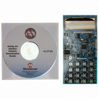
BOARD DEMO LCD GPIO EXP KEYPAD
Manufacturer
Microchip Technology
Datasheet
1.GPIODM-KPLCD.pdf
(28 pages)
Specifications of GPIODM-KPLCD
Main Purpose
Interface, Front Panel Controller, LCD
Embedded
Yes, MCU, 8-Bit
Utilized Ic / Part
MCP23008, MCP23S08, MCP23017, MCP23S17, PIC18F4550, MCP1702
Primary Attributes
(2) 8-Bit and (2) 16-Bit GPIO Expanders, 4x4 Keypad, 2x16 LCD
Secondary Attributes
Headers for the MCP23x08 and MCP23x17
Silicon Manufacturer
Microchip
Core Architecture
PIC
Core Sub-architecture
PIC18
Features
SPI And I2C Buses, Keypad And LCD Interface, ICSP Header
Kit Contents
Board
Silicon Core Number
PIC18F
Silicon Family Name
PIC18F4xxx
Rohs Compliant
Yes
Lead Free Status / RoHS Status
Not applicable / Not applicable
For Use With
MCP23S08/17, MCP23008/17
Lead Free Status / RoHS Status
Lead free / RoHS Compliant, Not applicable / Not applicable


2.4
© 2006 Microchip Technology Inc.
GPIO EXPANDER KEYPAD AND LCD DEMO BOARD DESCRIPTION
2.4.1
The functional block diagram is shown in
FIGURE 2-2:
1. The GPIO BLOCK contains the MCP23X17 and MCP23X08 GPIO Expanders.
2. The CONTROL BLOCK contains the PIC18F4550 and is the main intelligence
3. The INPUT BLOCK contains the 4x4 keypad matrix. The MCP23X08 devices
4. The OUTPUT BLOCK contains the 2x16 LCD. The MCP23X17 devices control
5. The MCP23X17 and MCP23X08 I/O and serial lines are routed to the HEADER
6. The PROGRAMMING BLOCK contains the ICSP™ header for program-
7. The POWER BLOCK contains the MCP1702 5V voltage regulator. The board
Two (2) MCP23X17 devices are connected to the LCD module and two (2)
MCP23X08 devices are connected to the keypad matrix.
A button on the keypad toggles between I
the MCP23017 and MCP23008 are controlled by the PIC MCU. When in SPI
mode, the MCP23S17 and MCP23S08 are controlled. Only one (1) MCP23X08
and one (1) MCP23X17 is on the bus at a time.
in the system.
are used to scan the keys.
the display.
BLOCK to allow the pins to be probed.
ming/debugging the PIC18F4550.
can be powered by a 9V supply (connected through the power jack) or by
applying 5V directly to the power points.
Major Board Components
Input
Power
FUNCTIONAL BLOCK DIAGRAM
IN
Header
Control
GPIO
Figure
2
C and SPI mode. When in I
2-2.
OUT
Programming
2 X 16 LCD
DS51636A-page 9
Output
2
C mode,
Related parts for GPIODM-KPLCD
Image
Part Number
Description
Manufacturer
Datasheet
Request
R

Part Number:
Description:
Manufacturer:
Microchip Technology Inc.
Datasheet:
Part Number:
Description:
Manufacturer:
Microchip Technology Inc.
Datasheet:
Part Number:
Description:
Manufacturer:
Microchip Technology Inc.
Datasheet:
Part Number:
Description:
Manufacturer:
Microchip Technology Inc.
Datasheet:
Part Number:
Description:
Manufacturer:
Microchip Technology Inc.
Datasheet:
Part Number:
Description:
Manufacturer:
Microchip Technology Inc.
Datasheet:
Part Number:
Description:
Manufacturer:
Microchip Technology Inc.
Datasheet:
Part Number:
Description:
Manufacturer:
Microchip Technology Inc.
Datasheet: