MCP2515DM-BM Microchip Technology, MCP2515DM-BM Datasheet - Page 55
MCP2515DM-BM
Manufacturer Part Number
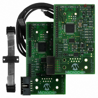
MCP2515DM-BM
Description
BOARD DEMO FOR MCP2515/51
Manufacturer
Microchip Technology
Series
PICtail™r
Specifications of MCP2515DM-BM
Main Purpose
Interface, CAN Controller
Embedded
Yes, MCU, 8-Bit
Utilized Ic / Part
MCP2515, MCP2551
Primary Attributes
Stand alone CAN Controller with SPI
Silicon Manufacturer
Microchip
Silicon Core Number
MCP2515, MCP2551
Features
Two Identical Boards And A CAN Cable For Creating A Small CAN Bus, CAN Bus PC Software
Lead Free Status / RoHS Status
Lead free / RoHS Compliant
Secondary Attributes
-
Lead Free Status / RoHS Status
Lead free / RoHS Compliant
Available stocks
Company
Part Number
Manufacturer
Quantity
Price
Company:

Part Number:
MCP2515DM-BM
Manufacturer:
Microchip Technology
Quantity:
135


9.0
The MCP2515 differentiates between two resets:
1.
2.
Both of these resets are functionally equivalent. It is
important to provide one of these two resets after
power-up to ensure that the logic and registers are in
their default state. A hardware reset can be achieved
automatically by placing an RC on the RESET pin (see
Figure
held in reset for a minimum of 2 µs after V
operating voltage, as indicated in the electrical
specification (t
FIGURE 9-1:
© 2010 Microchip Technology Inc.
Hardware Reset – Low on RESET pin
SPI Reset – Reset via SPI command
9-1). The values must be such that the device is
RESET
RL
Note 1: The diode D helps discharge the capacitor quickly when V
).
2: R1 = 1 kΩ to 10 kΩ will limit any current flowing into RESET from external
RESET PIN CONFIGURATION EXAMPLE
capacitor C, in the event of RESET pin breakdown due to Electrostatic
Discharge (ESD) or Electrical Overstress (EOS).
V
DD
D
(1)
DD
V
reaches
DD
R
C
R1
(2)
RESET
DD
powers down.
MCP2515
DS21801F-page 55
Related parts for MCP2515DM-BM
Image
Part Number
Description
Manufacturer
Datasheet
Request
R

Part Number:
Description:
IC CAN CONTROLLER W/SPI 18SOIC
Manufacturer:
Microchip Technology
Datasheet:

Part Number:
Description:
IC CAN CONTROLLER W/SPI 18DIP
Manufacturer:
Microchip Technology
Datasheet:
Part Number:
Description:
IC CAN CONTROLLER W/SPI 18SOIC
Manufacturer:
Microchip Technology
Datasheet:

Part Number:
Description:
IC CAN CONTROLLER W/SPI 20TSSOP
Manufacturer:
Microchip Technology
Datasheet:
Part Number:
Description:
IC CAN CONTROLLER W/SPI 20TSSOP
Manufacturer:
Microchip Technology
Datasheet:

Part Number:
Description:
IC,LAN TRANSCEIVER,SINGLE,CMOS,DIP,18PIN,PLASTIC
Manufacturer:
Microchip Technology
Datasheet:
Part Number:
Description:
CAN controller with SPI interface, 125 deg C, -40C to +125C, 18-PDIP, TUBE
Manufacturer:
Microchip Technology
Datasheet:

Part Number:
Description:
Manufacturer:
Microchip Technology Inc.
Datasheet:
Part Number:
Description:
Manufacturer:
Microchip Technology Inc.
Datasheet:
Part Number:
Description:
Manufacturer:
Microchip Technology Inc.
Datasheet:
Part Number:
Description:
Manufacturer:
Microchip Technology Inc.
Datasheet:
Part Number:
Description:
Manufacturer:
Microchip Technology Inc.
Datasheet: