MCP3421DM-BFG Microchip Technology, MCP3421DM-BFG Datasheet - Page 14
MCP3421DM-BFG
Manufacturer Part Number
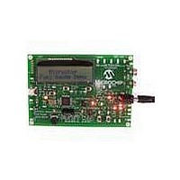
MCP3421DM-BFG
Description
BOARD DEMO FOR MCP3421
Manufacturer
Microchip Technology
Datasheets
1.MCP3421A2T-ECH.pdf
(42 pages)
2.MCP3421DM-BFG.pdf
(26 pages)
3.MCP3421A0T-ECH.pdf
(30 pages)
Specifications of MCP3421DM-BFG
Main Purpose
Power Management, Battery Gauge
Utilized Ic / Part
MCP3421
Processor To Be Evaluated
MCP3421
Lead Free Status / RoHS Status
Lead free / RoHS Compliant
Secondary Attributes
-
Embedded
-
Primary Attributes
-
Lead Free Status / RoHS Status
Lead free / RoHS Compliant, Lead free / RoHS Compliant


MCP3421 Battery Fuel Gauge Demo Board User’s Guide
DS51683A-page 10
2.1.4
This demo board has a buzzer. The buzzer beeps when the board is first powered up
and also when the battery fuel is consumed 50% or less, or the battery is disconnected.
2.1.5
This board has a USB connector for the PIC18F4550. The current firmware version for
the PIC18F4550 is not including the USB interface feature.
2.1.6
The MCP3421 Battery Fuel Gauge Demo Board includes the PIC18F4550. This MCU
is used to control the data acquisition devices (ADC) and compute the fuel gauging
parameters. The MCU also sends characters to the LCD.
The board has an 8-pin connector for the ICD In-Circuit Serial Programming™
(ICSP™). The MCU source code is written in assembly language. The user can modify
the code for their own experiment using the MPLAB ICD2 Programmer. The user needs
an ICD-2 ICSP adapter socket (P/N: AC164110) between the MPLAB ICD2 Program-
mer and the MCP3421 Battery Fuel Gauge Demo Board.
2.1.7
The MCP3421 Battery Fuel Gauge Demo Board uses two jumpers, JP1 and JP2. JP1
is used to provide a battery discharge path. Connect JP1 (while JP2 is disconnected)
when testing battery discharging. Contact Microchip Technology Inc., if you need the
battery charging mode.
2.1.8
The MCP3421 Battery Fuel Gauge Demo Board has 5 push button switches.
• SW1 is used to enter the battery fuel gauging mode.
• SW2, SW3, SW4: are not Used.
• Reset SW is the MCLR reset pin switch and is used to reset the MCU.
2.1.9
This potentiometer is used to calibrate the input voltage to the ADC and is calibrated
before shipping to the customer. If the customer wants to calibrate, then refer to Step 5
of the calibration procedure in Section 2.2.1 “Battery Fuel Measurement”.
2.1.10
The MCP3421 Battery Fuel Gauge Demo Board has various test points to capture the
communication between the MCU and ADC devices. The user can see the I
communication data streams at SCL and SDA test pins using an oscilloscope. The
SYNC terminal is used as a “trigger” source when the SCL and SDA signals are
captured. The board also has the test terminals for the battery charger (U3): Prog 1,
Prog 2 and C-STAT terminals.
Note:
Interface to MPLAB
Jumper
Push Button Switches
Potentiometer (R1)
Do not connect both JP1 and JP2 at the same time.
Buzzer
USB Connector
Signal Outputs
Draft
®
ICD2 Programmer
© 2007 Microchip Technology Inc.
2
C
Related parts for MCP3421DM-BFG
Image
Part Number
Description
Manufacturer
Datasheet
Request
R

Part Number:
Description:
18-Bit Analog-to-Digital Converter with I2C Interface and On-Board Reference
Manufacturer:
Microchip Technology
Datasheet:

Part Number:
Description:
Manufacturer:
Microchip Technology Inc.
Datasheet:
Part Number:
Description:
Manufacturer:
Microchip Technology Inc.
Datasheet:
Part Number:
Description:
Manufacturer:
Microchip Technology Inc.
Datasheet:
Part Number:
Description:
Manufacturer:
Microchip Technology Inc.
Datasheet:
Part Number:
Description:
Manufacturer:
Microchip Technology Inc.
Datasheet:
Part Number:
Description:
Manufacturer:
Microchip Technology Inc.
Datasheet:
Part Number:
Description:
Manufacturer:
Microchip Technology Inc.
Datasheet:
Part Number:
Description:
Manufacturer:
Microchip Technology Inc.
Datasheet: