MCP3909RD-1PH1 Microchip Technology, MCP3909RD-1PH1 Datasheet - Page 23
MCP3909RD-1PH1
Manufacturer Part Number
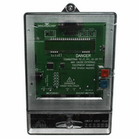
MCP3909RD-1PH1
Description
BOARD DES MCP3909 ENERGY METER
Manufacturer
Microchip Technology
Datasheets
1.MCP3909T-ISS.pdf
(44 pages)
2.MCP3909RD-1PH1.pdf
(60 pages)
3.MCP3909RD-1PH1.pdf
(6 pages)
Specifications of MCP3909RD-1PH1
Main Purpose
Power Management, Energy/Power Meter
Embedded
Yes, MCU, 8-Bit
Utilized Ic / Part
MCP3909, PIC18F85J90
Primary Attributes
Single Phase Shunt Energy Meter
Secondary Attributes
16 Bit ADC
Ic Function
Single Phase Energy Measurement IC
Supply Voltage Range
4.5V To 5.5V
Operating Temperature Range
-40°C To +85°C
Digital Ic Case Style
SSOP
No. Of Pins
24
Interface Type
SPI
Lead Free Status / RoHS Status
Contains lead / RoHS non-compliant
Lead Free Status / RoHS Status
Contains lead / RoHS non-compliant


TABLE 4-2:
The
integration times and, thus, higher frequencies. The
output frequency value can be calculated with the
following equation:
EQUATION 4-2:
The constant HF
digital settings with the
The detailed timings of the output pulses are described
in the Timing Characteristics table (see Section 1.0
“Electrical Characteristics” and
TABLE 4-3:
© 2009 Microchip Technology Inc.
Where:
F2
F1
V
0
0
0
0
1
1
1
1
0
0
1
1
HF
REF
high-frequency
V
V
HF
G = the PGA gain on Channel 0
C
0
1
OUT
= the RMS differential voltage on
= the RMS differential voltage on
= the frequency constant selected
= the voltage reference
F1
0
0
1
1
0
0
1
1
(
F0
0
1
0
1
Hz
Channel 0
Channel 1
(current channel)
C
ACTIVE POWER OUTPUT FREQUENCY CONSTANT F
)
F0
OUTPUT FREQUENCY CONSTANT HF
0
1
0
1
0
1
0
1
depends on the F
=
ACTIVE POWER HF
FREQUENCY OUTPUT
EQUATION
8.06
--------------------------------------------------------------- -
Table
output
MCLK/2
MCLK/2
MCLK/2
MCLK/2
F
2048 x F
×
128 x F
C
64 x F
32 x F
16 x F
64 x F
32 x F
16 x F
V
4-3.
HF
(Hz)
0
(
V
×
C
HF
REF
21
20
19
18
V
Figure
C
C
C
C
C
C
1
C
C
OUT
×
)
2
OUT0
G
×
1-1).
(MCLK = 3.58 MHz)
HF
has
and F
C
OUT
MCLK/2
MCLK/2
MCLK/2
MCLK/2
MCLK/2
MCLK/2
MCLK/2
MCLK/2
HF
F
lower
OUT1
13.66
C
C
1.71
3.41
6.83
(Hz)
(Hz)
15
15
15
16
16
16
16
7
4.8.1
The MCP3909 also includes, on each output
frequency, a no-load threshold circuit that will eliminate
any creep effects in the meter. The outputs will not
show any pulse if the output frequency falls below the
no-load threshold. This threshold only applies to the
pulse outputs and does not gate any serial data coming
from either the A/D output or the multiplier output. The
minimum output frequency on F
equal to 0.0015% of the maximum output frequency
(respectively F
selections (see
F2, F1, F0 = 011. In this last configuration, the no-load
threshold feature is disabled. The selection of F
determine the start-up current load. In order to respect
the IEC standards requirements, the meter will have to
be designed to allow start-up currents compatible with
the standards by choosing the FC value matching
these
information on no-load threshold, startup current and
other
"IEC Compliant Active Energy Meter Design Using The
MCP3905/6”, (DS00994).
C
(MCLK = 3.58 MHz)
FOR HF
F
OUT
27968.75
HF
with Full-Scale
109.25
109.25
109.25
219.51
219.51
219.51
219.51
meter
requirements.
C
Frequency (Hz)
DC Inputs
(Hz)
MINIMAL OUTPUT FREQUENCY
FOR NO-LOAD THRESHOLD
OUT
0.74
1.48
2.96
5.93
C
Table 4-2
design
and HF
(V
C
REF
FOR FOUT0/1 (V
C
For
HF
= 2.4V)
) for each of the F2, F1 and F0
points,
and
OUT
full scale AC Inputs
MCP3909
F
Table
additional
OUT
Frequency (Hz) with
OUT0/1
with Full-Scale
6070.12
refer
27.21
27.21
27.21
47.42
47.42
47.42
47.42
Frequency (Hz)
AC Inputs
4-3); except when
DS22025B-page 23
0.37
0.74
1.48
2.96
REF
and HF
to
applications
= 2.4V)
AN994,
OUT
C
will
is
Related parts for MCP3909RD-1PH1
Image
Part Number
Description
Manufacturer
Datasheet
Request
R

Part Number:
Description:
REF DESIGN FOR MCP3909 W/18F2520
Manufacturer:
Microchip Technology
Datasheet:

Part Number:
Description:
REF DESIGN MCP3909 3PH ENGY MTR
Manufacturer:
Microchip Technology
Datasheet:

Part Number:
Description:
Manufacturer:
Microchip Technology Inc.
Datasheet:
Part Number:
Description:
Manufacturer:
Microchip Technology Inc.
Datasheet:
Part Number:
Description:
Manufacturer:
Microchip Technology Inc.
Datasheet:
Part Number:
Description:
Manufacturer:
Microchip Technology Inc.
Datasheet:
Part Number:
Description:
Manufacturer:
Microchip Technology Inc.
Datasheet:
Part Number:
Description:
Manufacturer:
Microchip Technology Inc.
Datasheet:
Part Number:
Description:
Manufacturer:
Microchip Technology Inc.
Datasheet:
Part Number:
Description:
Manufacturer:
Microchip Technology Inc.
Datasheet: