EVAL-ADUM4160EBZ Analog Devices Inc, EVAL-ADUM4160EBZ Datasheet

EVALUATION MODULE FOR ADUM4160

EVAL-ADUM4160EBZ

Manufacturer Part Number
EVAL-ADUM4160EBZ
Description
EVALUATION MODULE FOR ADUM4160
Manufacturer
Analog Devices Inc
Series
iCoupler®r

Specifications of EVAL-ADUM4160EBZ

Main Purpose
Interface, Digital Isolator
Embedded
No
Utilized Ic / Part
ADuM4160
Primary Attributes
USB Bidirectional Isolation
Secondary Attributes
3.1 V ~ 5.5 V Supply
Silicon Manufacturer
Analog Devices
Application Sub Type
USB Port Isolator
Kit Application Type
Interface
Silicon Core Number
ADuM4160
Lead Free Status / RoHS Status
Lead free / RoHS Compliant
Lead Free Status / RoHS Status
Lead free / RoHS Compliant, Lead free / RoHS Compliant
Other names
Q4508819
INTRODUCTION
USB use has displaced older communications standards, such
as RS-232, as the default serial communications port in PC-based
systems. When compared to these other standards, USB has
many enhanced features, such as power for peripherals, automatic
driver installation, and higher data rates. However, when using
USB, it is difficult to provide isolation, which has limited its
acceptance in medical and industrial applications.
Analog Devices, Inc., has introduced the
ADuM3160
isolating the bus. The EVAL-ADuM4160EBZ USB isolator
evaluation board was constructed to allow an easy interface to
existing applications by standard cabling or discrete wiring.
The USB evaluation board comes populated with an
ADuM4160; however, because the ADuM4160 and ADuM3160
are electrically identical and pin compatible, any evaluation
done with this board and component applies directly to the
ADuM3160. If for some reason the user wants to substitute
theADuM3160 on the PCB, no other changes are required.
The design goals of this evaluation platform are to
Please see the last page for an important warning and disclaimers.
One Technology Way • P.O. Box 9106 • Norwood, MA 02062-9106, U.S.A. • Tel: 781.329.4700 • Fax: 781.461.3113 • www.analog.com
Connect to systems through standard USB Type A and
Type B connectors.
Draw power from the USB host or from an external 5.0 V
or 3.3 V power supply.
Support isolated power for the downstream interface
through an
Support external downstream power from a 5 V or 3.3 V
power supply.
Provide test points for all power and signal paths.
Support low and full speed communications.
Support enumeration control.
Support external ESD protection.
Support common-mode chokes in the xD+/xD− lines.
Support ferrite inductors in the V
USB isolators to address the difficult task of
ADuM5000
iCoupler ADuM4160/ADuM3160 USB Isolator Evaluation Board
isoPower® dc-to-dc converter.
BUSx
ADuM4160
and GND
x
lines.
and
Rev. A | Page 1 of 8
FEATURES OF THE ADuM4160/ADUM3160
The ADuM4160 and ADum3160 provide support for full speed
and low speed data communications by interfacing directly with
the USB xD+ and xD− lines. The parts are designed to be
transparent to USB data traffic other than adding about as
much delay as a hub and cable. Features of the isolator include
the following:
The upstream side of the isolator includes Pin 1 through Pin 8,
is connected to the left side of the evaluation board, and
interfaces through a Type B connector. The downstream facing
side includes Pin 9 through Pin 16, is connected to the right
side of the evaluation board, and interfaces through a Type A
connector.
The evaluation board allows configuration of all of the features of
the ADuM4160/ADuM3160 chip and provides support for a
variety of possible power schemes. The board also allows
common-mode voltages; however, it is not recommended for
performing safety related testing, such as high voltage withstand
testing. Perform this type of testing on the component level or on a
production board.
Evaluation Board User Guide
Built-in voltage regulators allow the ADuM4160 and
ADuM3160 to draw power from either 5 V or 3.3 V
sources.
Application of the upstream pull-up resistor is under the
control of a downstream pin, PIN (Pin 12).
The operating speed of the isolator is set by pins on the
upstream and downstream sides of the part, SPU and SPD
(Pin 5 and Pin 13, respectively).
EVALUATION BOARD
Figure 1. USB Evaluation Board
UG-043

Related parts for EVAL-ADUM4160EBZ

EVAL-ADUM4160EBZ Summary of contents

Page 1

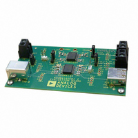
... Analog Devices, Inc., has introduced the ADuM3160 USB isolators to address the difficult task of isolating the bus. The EVAL-ADuM4160EBZ USB isolator evaluation board was constructed to allow an easy interface to existing applications by standard cabling or discrete wiring. The USB evaluation board comes populated with an ADuM4160 ...

Page 2

... Upstream Side ............................................................................... 3 Downstream Side.......................................................................... 3 Grounding Scheme ....................................................................... 3 REVISION HISTORY 9/10—Rev Rev. A Added ADuM3160 ........................................................ Throughout Changes to Introduction .................................................................. 1 2/10—Revision 0: Initial Version Evaluation Board User Guide Speed Selection ..............................................................................4 Pull-Up Control .............................................................................4 Series Resistors...............................................................................4 Test Points ......................................................................................4 Optional Components ..................................................................4 Evaluation Board Schematic and Artwork .....................................5 Rev. A| Page ...

Page 3

... The user can bypass this regulator if 3.3 V can be provided from an external supply. The evaluation board can source its power either from the cable from an external supply connected to terminal block J5, labeled EXT. Jumper JP1 selects between the two sources. When external power is chosen, the ADuM3160 and ADuM4160 can be configured to accept either 3 ...

Page 4

... USB transmission speed, either low speed or full speed. The speed is set by the SPU and SPD pins on the upstream and downstream sides of the part and must be set by jumpers on the evaluation board. Both speed jumpers must be set to the same speed setting for proper operation. ...

Page 5

... Evaluation Board User Guide EVALUATION BOARD SCHEMATIC AND ARTWORK TBD0805 R10 TBD0805 R9 TBD0805 R7 Figure 2. Evaluation Board Schematic Rev. A| Page UG-043 08418-002 ...

Page 6

... UG-043 Evaluation Board User Guide Figure 3. Evaluation Board Artwork Rev. A| Page ...

Page 7

... Evaluation Board User Guide NOTES Rev. A| Page UG-043 ...

Page 8

... Evaluation Board for any other purpose. Furthermore, the license granted is expressly made subject to the following additional limitations: Customer shall not (i) rent, lease, display, sell, transfer, assign, sublicense, or distribute the Evaluation Board; and (ii) permit any Third Party to access the Evaluation Board. As used herein, the term “ ...

Related keywords