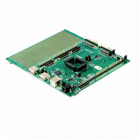
V2-EVAL FTDI, Future Technology Devices International Ltd, V2-EVAL Datasheet - Page 13

V2-EVAL
Manufacturer Part Number
V2-EVAL
Description
BOARD DEV FOR VINCULUM-II VNC2
Manufacturer
FTDI, Future Technology Devices International Ltd
Series
Vinculum-IIr
Datasheet
1.V2-EVAL-EXT32.pdf
(64 pages)
Specifications of V2-EVAL
Main Purpose
USB Controller
Embedded
Yes, ASIC
Utilized Ic / Part
VNC2-32Q
Primary Attributes
1 type-B and 2 type-A USB connectors
Secondary Attributes
User Configurable LEDs
Lead Free Status / RoHS Status
Lead free / RoHS Compliant
Other names
768-1062
- Current page: 13 of 64
- Download datasheet (3Mb)
Document Reference No.: FT_000247
V2-EVAL Vinculum II Evaluation Board Datasheet Version 2.0
Clearance No.: FTDI#148
4.2
Testing the board.
Ensure that the Power Select jumper JP6 is in „P.S.‟ position (pins 2 & 3 shorted), to enable the board to
be powered from the external power adapter.
Connect the 5V DC/1A power supply included in V2-Eval Kit to the external input power adapter
connector (CN12), connect USB A/B cable to USB B connector (CN13) on V2-Eval Board and to a free
USB port on host PC. Switch SW1 to the ON position (towards board edge). LED2 – POWER should now
be on.
Figure 4.2
Power connector with Jumper JP6
The PCB circuitry will draw power either directly from the board 5V supply or from a 3.3V regulator that is
powered by this 5V supply. This includes the VNC2 daughterboard module that is installed on the board.
Upon power up, the power LED (LED2) will illuminate.
Copyright © 2010 Future Technology Devices International Limited
12
Related parts for V2-EVAL
Image
Part Number
Description
Manufacturer
Datasheet
Request
R

Part Number:
Description:
IC USB TO SERIAL UART 32-QFN
Manufacturer:
FTDI, Future Technology Devices International Ltd

Part Number:
Description:
IC USB HOST CTLR VINCULUM 48LQFP
Manufacturer:
FTDI, Future Technology Devices International Ltd
Datasheet:

Part Number:
Description:
IC USB HOST VINCULUM-II 32QFN
Manufacturer:
FTDI, Future Technology Devices International Ltd
Datasheet:

Part Number:
Description:
IC USB HOST VINCULUM-II 32LQFN
Manufacturer:
FTDI, Future Technology Devices International Ltd
Datasheet:

Part Number:
Description:
IC USB HOST VINCULUM-II 48QFN
Manufacturer:
FTDI, Future Technology Devices International Ltd
Datasheet:

Part Number:
Description:
IC USB HOST VINCULUM-II 32LQFN
Manufacturer:
FTDI, Future Technology Devices International Ltd
Datasheet:

Part Number:
Description:
IC USB HOST VINCULUM-II 32QFN
Manufacturer:
FTDI, Future Technology Devices International Ltd
Datasheet:

Part Number:
Description:
IC USB HOST VINCULUM-II 48LQFP
Manufacturer:
FTDI, Future Technology Devices International Ltd
Datasheet:

Part Number:
Description:
IC USB HOST VINCULUM-II 48LQFP
Manufacturer:
FTDI, Future Technology Devices International Ltd
Datasheet:

Part Number:
Description:
IC USB HOST VINCULUM-II 48QFN
Manufacturer:
FTDI, Future Technology Devices International Ltd
Datasheet:

Part Number:
Description:
IC USB HOST CTLR VINCULUM 64QFN
Manufacturer:
FTDI, Future Technology Devices International Ltd
Datasheet:

Part Number:
Description:
IC USB HOST CTLR VINCULUM 64LQFP
Manufacturer:
FTDI, Future Technology Devices International Ltd
Datasheet:

Part Number:
Description:
IC USB HOST VINCULUM-II 64LQFP
Manufacturer:
FTDI, Future Technology Devices International Ltd
Datasheet:

Part Number:
Description:
IC USB HOST VINCULUM-II 64QFN
Manufacturer:
FTDI, Future Technology Devices International Ltd
Datasheet:

Part Number:
Description:
IC USB TO PARALLEL FIFO 28-SSOP
Manufacturer:
FTDI, Future Technology Devices International Ltd
Datasheet:


