EVAL-AD7877EBZ Analog Devices Inc, EVAL-AD7877EBZ Datasheet
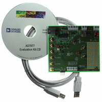
BOARD EVALUATION FOR AD7877

EVAL-AD7877EBZ

Manufacturer Part Number
EVAL-AD7877EBZ
Description
BOARD EVALUATION FOR AD7877
Manufacturer
Analog Devices Inc

Specifications of EVAL-AD7877EBZ

Main Purpose
Interface, Touch Screen Controller
Embedded
No
Utilized Ic / Part
AD7877
Primary Attributes
4-Wire Resistive Touch Screen Controller, SPI Interface, On-Chip: Temp Sensor, Voltage Reference, 8-Bit DAC
Secondary Attributes
USB GUI, LCD Noise Reduction Feature, 2.7 ~ 5.25 V, Wake Up on Touch Feature
Lead Free Status / RoHS Status
Lead free / RoHS Compliant
GENERAL DESCRIPTION
The AD7877 is a 12-bit successive approximation ADC with a
synchronous serial interface and low on resistance switches for
driving touch screens. The AD7877 operates from a single
2.7 V to 5.25 V power supply (functional operation to 2.2 V)
and features throughput rates of 125 kSPS.
The AD7877 features direct battery measurement on two
inputs, temperature measurement, and touch-pressure measure-
ment. The AD7877 also has an on-board reference of 2.5 V.
When not in use, it can be shutdown to conserve power. An
external reference can also be applied and can be varied from
1 V to +V
The device includes a shutdown mode that reduces the current
consumption to less than 1 A.
To reduce the effects of noise from LCDs, the acquisition phase
of the on-board ADC may be controlled via the STOPACQ
pin. There is also an on-board DAC for LCD backlight or con-
trast control. The AD7877 can run in either a slave or master
mode, using a conversion sequencer and timer. It is ideal for
battery-powered systems, such as personal digital assistants with
resistive touch screens and other portable equipment. The part
is available in a 32-lead LFCSP.
REV. Sp0
Information furnished by Analog Devices is believed to be accurate and
reliable. However, no responsibility is assumed by Analog Devices for its
use, nor for any infringements of patents or other rights of third parties that
may result from its use. No license is granted by implication or otherwise
under any patent or patent rights of Analog Devices. Trademarks and
registered trademarks are the property of their respective owners.
AD7877 FEATURES
4-Wire Touch Screen Interface
LCD Noise Reduction Feature (STOPACQ Pin)
On-Chip Temperature Sensor: –40 C to +85 C
On-Chip 2.5 V Reference
On-Chip 8-Bit DAC
Three Auxiliary Analog Inputs
One Dedicated and Three Optional GPIOs
Two Direct Battery Measurement Channels
Three Interrupt Outputs
Automatic Conversion Sequencer and Timer
Touch-Pressure Measurement
Wake Up on Touch Function
Specified Throughput Rate of 125 kSPS
Single Supply, V
ESD Protection on All Analog Pins
Shutdown Mode: 1 A Max
APPLICATIONS
Personal Digital Assistants
Smart Hand-Held Devices
Touch-Screen Monitors
Point-of-Sales Terminals
Pagers
(0.5 V to 5 V)
CC
, while the analog input range is from 0 V to V
CC
of 2.7 V to 5.25 V
REF
.
EVALUATION SYSTEM PACKAGE CONTENTS
The evaluation system contains the following items:
EVALUATION BOARD DESCRIPTION
The user can use this evaluation board to fully investigate all
features of the AD7877 touch screen controller.
The AD7877 evaluation board plugs directly into the USB port
on a standard PC. An on-board USB controller IC interfaces
directly to the AD7877 and gives the evaluation software full
control of the AD7877 registers. A MicroTouch touch screen is
included in this evaluation kit and can be plugged directly into
the AD7877 evaluation board.
This evaluation board contains the following main components
that can be identified from the block diagram in Figure 1. The
printed circuit board (PCB) schematic and silk screen are shown
in Figures 12 through 14.
One Technology Way, P.O. Box 9106, Norwood, MA 02062-9106, U.S.A.
Tel: 781/329-4700
Fax: 781/326-8703
The EVAL-AD7877 Evaluation Board
USB Cable
Evaluation Software
MicroTouch
Stylus
AD7877 IC
USB Microcontroller IC CY7C68013
LED indicators for power, PENIRQ, ALERT, and
THERM
EEPROM for USB initialization information
Connector for USB interface
Connector for touch screen
Sub-BNC connectors for the following signals: BAT1,
BAT2, AUX1/GPIO1, AUX2/GPIO2, AUX3/GPIO3,
STOPACQ, GPIO4, and A
Screw-top connectors for the following signals: V
X+, Y+, X–, Y–, V
Test points for the following signals: DOUT, DIN, DCLK,
CS, DAV, PENIRQ, and A
Evaluation Board for AD7877
Touch Screen Controller
Touch Screen
© 2003 Analog Devices, Inc. All rights reserved.
REF
, and V
EVAL-AD7877
OUT
OUT
DRIVE
www.analog.com
CC
, GND,
*

Related parts for EVAL-AD7877EBZ

EVAL-AD7877EBZ Summary of contents

Page 1

... PC. An on-board USB controller IC interfaces directly to the AD7877 and gives the evaluation software full control of the AD7877 registers. A MicroTouch touch screen is included in this evaluation kit and can be plugged directly into the AD7877 evaluation board. This evaluation board contains the following main components that can be identified from the block diagram in Figure 1 ...

Page 2

... J2-1 J2-2 J2-3 J2-4 J12-2 J12-4 J12-1 J12-3 Figure 1. AD7877 Evaluation Board Block Diagram CONNECTOR FUNCTION DESCRIPTIONS Description These screw-top connectors can be used to supply V To supply an external V , Link 4 should be in the B position, and the signal applied REF to J15-1. To supply an external V signal applied to J15-2. ...

Page 3

... REF left open or in Position B with J15-1 left floating. This jumper selects the input power for the evaluation board. If the jumper is in Position A, power for the board must be supplied through Connector J13. If the link is in Position B, the USB connection supplies the power for the board. ...

Page 4

... CD-ROM drive. To finish installing the software, follow the on screen instructions. RUNNING THE SOFTWARE When using the software, first ensure the evaluation board is connected to the PC via the USB cable. To run the software, select Start/Programs/Analog Devices/AD7877 Eval Software. When the program is started, the About screen, shown in Figure 2, is displayed ...

Page 5

... PC and the board is active. If this dot is red, the connection is not functional. In this situation, the user should check that the USB port on their PC is con- figured correctly and that the evaluation board is connected via the USB connector to the PC. Reading and Writing to the Registers The register access screen gives access to all the registers on the AD7877. A map of the AD7877’ ...

Page 6

... EVAL-AD7877 Figure 4. Accessing the TEMP2 Register Figure 5. Accessing the Y+ Register –6– REV. Sp0 ...

Page 7

... The limits may be changed by dragging the limit bars up or down. The new limits are automatically written to the relevant AD7877 registers by the evaluation software. The AUX1, BAT1, BAT2, and Temp1 channels all have upper and lower limits. Also displayed next to these channels in the list is an ALERT button. If the button is green, the channel’ ...

Page 8

... Easy Setup Clicking on the Easy Setup button at the bottom of the Visual Display screen sets the AD7877 up and running. The evaluation software writes to the AD7877 to set up the registers. The software then programs the device to perform a measurement on each channel. The software reads back the result of each measurement before going on to the next and then this cycle is repeated ...

Page 9

... The user can change this to any value, with the minimum value being 5 ms. This is the default value. If monitoring is disabled, then the evaluation software stops reading data from the AD7877. Enable graphing: This controls whether the selected measure- ment is graphed on the graphing window ...

Page 10

... The STOPACQ input signal polarity can be selected by the user very important that the user selects the correct polar- ity for the signal applied to the STOPACQ input of the evaluation board. If the wrong polarity is selected, the ADC on the AD7877 will stop acquiring data and no new measurements will be made. ...

Page 11

... Figure 12. AD7877 Evaluation Board Schematic AD7877 Section REV. Sp0 DCLK AGND DOUT DGND DRIVE V Y+ RNG A X+ OUT A Y– REF V X– –11– EVAL-AD7877 ...

Page 12

... R15 100k 100k C15 0.1 F C24 + C11 10 F 0.1 F 10V DGND DGND DGND DIND CLK CS PENRIQ DOUT DAV DIN DCLK CS PENIRQ DOUT DAV Figure 13. AD7877 Evaluation Board Schematic USB Section C20 C21 C22 0.1 F 0.1 F 0.1 F DGND 0.1 F 3.3V 3. SCL 4 VSS ...

Page 13

... Figure 15. AD7877 Evaluation Board Component Side Artwork REV. Sp0 Figure 14. AD7877 Evaluation Board Silkscreen –13– EVAL-AD7877 ...

Page 14

... EVAL-AD7877 Figure 16. AD7877 Evaluation Board Solder Side Artwork Name Type C1, C6 CAP C2 to C5, C7, C9 CAP C8, C10 CAP+ C11, C15 to C23 CAP C12, C13 CAP C14 CAP+ C24 CAP+ D1, D2, D3 LED J2, J10, J13, J15 CON/POWER J3 to J9, J11 SMB J12 CON-SIP-4P_SMD J14 USB ...

Page 15

–15– ...

Page 16

–16– ...

Related keywords