EVAL-ADM1066LFEB Analog Devices Inc, EVAL-ADM1066LFEB Datasheet - Page 30
EVAL-ADM1066LFEB
Manufacturer Part Number
EVAL-ADM1066LFEB
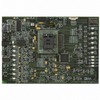
Description
BOARD EVALUATION FOR ADM1066LF
Manufacturer
Analog Devices Inc
Specifications of EVAL-ADM1066LFEB
Main Purpose
Power Management, Power Supply Supervisor/Tracker/Sequencer
Embedded
No
Utilized Ic / Part
ADM1066
Primary Attributes
10 Channel Supervisor / Sequencer, 6 Voltage Output DACs
Secondary Attributes
GUI Programmable via SMBus (via USB)
Lead Free Status / RoHS Status
Contains lead / RoHS non-compliant


ADM1066
Unlike some EEPROM devices that limit block writes to within
a page boundary, there is no limitation on the start address
when performing a block write to EEPROM, except when
•
•
Note that the ADM1066 features a clock extend function for writes
to the EEPROM. Programming an EEPROM byte takes approxi-
mately 250 μs, which limits the SMBus clock for repeated or block
write operations. The ADM1066 pulls SCL low and extends the
clock pulse when it cannot accept any more data.
READ OPERATIONS
The ADM1066 uses the following SMBus read protocols.
Receive Byte
In a receive byte operation, the master device receives a single
byte from a slave device, as follows:
1.
2.
3.
4.
5.
6.
In the ADM1066, the receive byte protocol is used to read a
single byte of data from a RAM or EEPROM location whose
address has previously been set by a send byte or write
byte/word operation, as shown in Figure 45.
Block Read
In a block read operation, the master device reads a block of
data from a slave device. The start address for a block read must
have been set previously. In the ADM1066, this is done by a
send byte operation to set a RAM address, or a write byte/word
operation to set an EEPROM address. The block read operation
itself consists of a send byte operation that sends a block read
command to the slave, immediately followed by a repeated start
and a read operation that reads out multiple data bytes, as follows:
1.
2.
3.
4.
There must be at least N locations from the start address to
the highest EEPROM address (0xFBFF) to avoid writing to
invalid addresses.
An address crosses a page boundary. In this case, both
pages must be erased before programming.
The master device asserts a start condition on SDA.
The master sends the 7-bit slave address followed by the
write bit (low).
The addressed slave device asserts an ACK on SDA.
The master sends a command code that tells the slave
device to expect a block read. The ADM1066 command
code for a block read is 0xFD (1111 1101).
The master device asserts a start condition on SDA.
The master sends the 7-bit slave address followed by the
read bit (high).
The addressed slave device asserts an ACK on SDA.
The master receives a data byte.
The master asserts a NACK on SDA.
The master asserts a stop condition on SDA, and the
transaction ends.
Figure 45. Single Byte Read from the EEPROM or RAM
S
1
ADDRESS
SLAVE
2
R
3
A
DATA
4
A
5
6
P
Rev. D | Page 30 of 32
5.
6.
7.
8.
9.
10. The master asserts an ACK on SDA.
11. The master receives 32 data bytes.
12. The master asserts an ACK on SDA after each data byte.
13. The master asserts a stop condition on SDA to end the
Error Correction
The ADM1066 provides the option of issuing a packet error correc-
tion (PEC) byte after a write to the RAM, a write to the EEPROM,
a block write to the RAM/EEPROM, or a block read from the
RAM/EEPROM. This option enables the user to verify that the data
received by or sent from the ADM1066 is correct. The PEC byte
is an optional byte sent after the last data byte has been written
to or read from the ADM1066. The protocol is the same as a
block read for Step 1 to Step 12 and then proceeds as follows:
13. The ADM1066 issues a PEC byte to the master. The master
14. A NACK is generated after the PEC byte to signal the end
15. The master asserts a stop condition on SDA to end the
Note that the PEC byte is calculated using CRC-8. The frame
check sequence (FCS) conforms to CRC-8 by the polynomial
See the SMBus Version 1.1 specification for details. An example
of a block read with the optional PEC byte is shown in Figure 47.
1
S
S
1
ADDRESS
ADDRESS
SLAVE
SLAVE
The slave asserts an ACK on SDA.
The master asserts a repeat start condition on SDA.
The master sends the 7-bit slave address followed by the
read bit (high).
The slave asserts an ACK on SDA.
The ADM1066 sends a byte-count data byte that tells the
master how many data bytes to expect. The ADM1066
always returns 32 data bytes (0x20), which is the maximum
allowed by the SMBus Version 1.1 specification.
transaction.
checks the PEC byte and issues another block read, if the
PEC byte is incorrect.
of the read.
transaction.
C ( x ) = x
2
2
Figure 47. Block Read from the EEPROM or RAM with PEC
W A
W A
Figure 46. Block Read from the EEPROM or RAM
8
3
3
+ x
COMMAND 0xFD
COMMAND 0xFD
(BLOCK READ)
(BLOCK READ)
2
+ x
4
4
1
+ 1
A
5
5
A
S
S
6
6
ADDRESS
ADDRESS
SLAVE
SLAVE
7
7
R A
R A
8
8
COUNT
COUNT
BYTE
BYTE
9
9
DATA
32
10
10
A
A
A
DATA
DATA
DATA
11
11
32
1
1
PEC
13
12
12
A
A
A
14
A
13
15
P
P
Related parts for EVAL-ADM1066LFEB
Image
Part Number
Description
Manufacturer
Datasheet
Request
R

Part Number:
Description:
IC, ADJ LDO REG, 1.5V TO 5V 250mA MSOP-8
Manufacturer:
Vishay
Datasheet:

Part Number:
Description:
IC, ADJ LDO REG, 1.5V TO 5V 0.6A 8-TSSOP
Manufacturer:
Vishay
Datasheet:
Part Number:
Description:
IC, ADJ LDO REG, 1.5V TO 5V 250mA MSOP-8
Manufacturer:
Vishay
Datasheet:

Part Number:
Description:
IC ADJ LDO REG 1.5V TO 5V 150mA 5-SOT-23
Manufacturer:
Vishay
Datasheet:

Part Number:
Description:
BOARD EVAL AS1324-AD
Manufacturer:
austriamicrosystems
Datasheet:
Part Number:
Description:
IC, ADJ LDO REG, 1.5V TO 5V 0.6A 8-TSSOP
Manufacturer:
Vishay
Datasheet:

Part Number:
Description:
IC, ADJ LDO REG, 1.5V TO 5V, 0.3A, MSOP8
Manufacturer:
Vishay
Datasheet:
Part Number:
Description:
IC, ADJ LDO REG, 1.5V TO 5V, 0.3A, MSOP8
Manufacturer:
Vishay
Datasheet:
Part Number:
Description:
IC, ADJ LDO REG 1.215V TO 5V 0.3A MSOP-8
Manufacturer:
Vishay
Datasheet:
Part Number:
Description:
IC, ADJ LDO REG 1.215V TO 5V 0.3A MSOP-8
Manufacturer:
Vishay
Datasheet:

Part Number:
Description:
±1.7g Dual-Axis IMEMS Accelerometer Evaluation Board
Manufacturer:
Analog Devices Inc
Datasheet:

Part Number:
Description:
IC MULTIPLIER ANALOG 8-SOIC T/R
Manufacturer:
Analog Devices Inc
Datasheet:

Part Number:
Description:
IC ANALOG MULTIPLIER 8-DIP
Manufacturer:
Analog Devices Inc
Datasheet:
Part Number:
Description:
IC ANALOG MULTIPLIER 8-SOIC
Manufacturer:
Analog Devices Inc
Datasheet:
Part Number:
Description:
IC ANALOG MULTIPLIER 8-DIP
Manufacturer:
Analog Devices Inc
Datasheet: