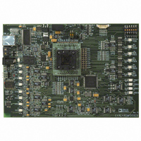
EVAL-ADM1064TQEB Analog Devices Inc, EVAL-ADM1064TQEB Datasheet - Page 22

EVAL-ADM1064TQEB
Manufacturer Part Number
EVAL-ADM1064TQEB
Description
BOARD EVALUATION FOR ADM1064TQ
Manufacturer
Analog Devices Inc
Specifications of EVAL-ADM1064TQEB
Main Purpose
Power Management, Power Supply Supervisor/Tracker/Sequencer
Embedded
No
Utilized Ic / Part
ADM1064
Primary Attributes
10 Channel Supervisor / Sequencer, 6 Voltage Output DACs
Secondary Attributes
GUI Programmable via SMBus (via USB)
Lead Free Status / RoHS Status
Contains lead / RoHS non-compliant
EVAL-ADM106x
Figure 35. Selecting an Input
SELECTING A FAULT TYPE
One of three fault types can be selected for each input:-
1.
2.
3.
The fault type is selected as shown in figure 35 below:-
Figure 36. Selecting an Out- of Window Fault
Under-voltage:- the input must fall below the programmed
threshold before a reset is generated
Over-voltage:- the input must rise above the programmed
threshold before a reset is generated
Out-of Window:- either an under-voltage or over-voltage fault
occurs.
Use the drop down box to
select an input to configure
Use the drop down
box to select a fault
Rev. PrB | Page 22 of 38
SELECTING A VOLTAGE RANGE
The input pins of the ADM106x can monitor supplies over a
wide range- from 0.573V to 14.4V. Not all inputs can monitor
over this range- the GUI shows over what range a given input
can detect faults. In order to maximize the resolution of the
programmed threshold, each input has a number of ranges.
These ranges overlap to ensure that any threshold can be
programmed over the full range of an input. The following
table shows the different ranges available at the inputs. Note
that different devices may have a different number of each
input however the range for each type of input will be the same.
These ranges are important when monitoring a supply and an
appropriate range for that supply should be selected to provide
maximum resolution.
VX1-VX5 are true High impedance inputs therefore a voltage
divider can be used to monitor voltages outside the specified
range. A voltage divider could also be employed at the VP
inputs however an input buffer would also be required.
36 below:-
Figure 37. Selecting an input range
The input range is selected in the software as shown in figure
INPUT
VX1-VX5
VP1 – VP4
VH
Table 5 Input voltage ranges
Preliminary Technical Data
Use the drop down
box to select a range
RANGE
1.25V – 3.0V
2.5V – 6.0V
6.0V – 14.4V
0.573V –1.375V
0.573V – 1.375V
2.5V – 6.0V


