CDB4265 Cirrus Logic Inc, CDB4265 Datasheet - Page 5
CDB4265
Manufacturer Part Number
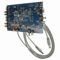
CDB4265
Description
BOARD EVAL FOR CS4265 CODEC
Manufacturer
Cirrus Logic Inc
Specifications of CDB4265
Main Purpose
Audio, CODEC
Embedded
No
Utilized Ic / Part
CS4265
Primary Attributes
Stereo, 24-Bit, 192 kHz Sample Rate
Secondary Attributes
Graphic User Interface, S/PDIF/ I2S / I2C / SPI Interface
Description/function
Audio CODECs
Operating Supply Voltage
5 V
Product
Audio Modules
For Use With/related Products
CS4265
Lead Free Status / RoHS Status
Contains lead / RoHS non-compliant
Lead Free Status / RoHS Status
Lead free / RoHS Compliant, Contains lead / RoHS non-compliant
Other names
598-1001


1.7
1.8
1.9
1.10 Serial Control Port
1.11 USB Control Port
DS657DB1
External Control Headers
The evaluation board has been designed to allow interfacing with external systems via the headers J15, and
J17.
The 14-pin, 2 row header, J15, provides access to the serial audio signals required to interface to the serial
audio port of the CS4265 with a DSP (see Figure 11).
The direction of the signals on header J15 can be configured using the controls located within the Board
Controls group box on the CDB4265 Controls tab in the provided GUI software.
The 12-pin, 3 row header, J17, allows the user bidirectional access to the SPI/I
removing all the shunt jumpers from the “PC” position. The user may then choose to connect a ribbon cable
to the “EXT CONTROL” position. A single “GND” row for the ribbon cable’s ground connection is provided
to maintain signal integrity. Two unpopulated pull-up resistors are also available should the user choose to
use the CDB for the I
Analog Inputs
RCA connectors supply the CS4265 analog inputs through single-ended, unity gain, active or passive cir-
cuits. Refer to the CS4265 data sheet for the ADC full-scale level.
A 4-pin CD-ROM type header is provided for easily connecting the analog outputs from a CD-ROM drive to
the analog inputs of the CS4265.
Analog Outputs
The CS4265 analog outputs are routed through a two-pole active filter. The output of the filter is connected
to RCA jacks for easy evaluation.
A graphical user interface is included with the CDB4265 to allow easy manipulation of the registers in the
CS4265, CS8416, and FPGA. See the device-specific data sheets for the CS4265, CS8416, and CD8406
internal register descriptions. The internal register map for the FPGA is located in section 4 on page 11.
Connecting a cable to the RS-232 connector (J19) and launching the Cirrus Logic FlexGUI software (Flex-
Loader.exe) will enable the CDB4265.
Refer to “PC Software Control” on page 7 for a description of the Graphical User Interface (GUI).
The USB control port connector (J29) is currently unavailable.
2
C power rail.
2
C control signals by simply
CDB4265
5
Related parts for CDB4265
Image
Part Number
Description
Manufacturer
Datasheet
Request
R

Part Number:
Description:
Development Kit
Manufacturer:
Cirrus Logic Inc
Datasheet:
Part Number:
Description:
Development Kit
Manufacturer:
Cirrus Logic Inc
Datasheet:


Part Number:
Description:
High-efficiency PFC + Fluorescent Lamp Driver Reference Design
Manufacturer:
Cirrus Logic Inc
Datasheet:
Part Number:
Description:
Development Kit
Manufacturer:
Cirrus Logic Inc
Datasheet:
Part Number:
Description:
Development Kit
Manufacturer:
Cirrus Logic Inc
Datasheet:

Part Number:
Description:
Development Kit
Manufacturer:
Cirrus Logic Inc
Datasheet:
Part Number:
Description:
Development Kit
Manufacturer:
Cirrus Logic Inc
Datasheet:
Part Number:
Description:
Development Kit
Manufacturer:
Cirrus Logic Inc
Datasheet:
Part Number:
Description:
Development Kit
Manufacturer:
Cirrus Logic Inc
Datasheet:

Part Number:
Description:
EVALUATION BOARD FOR CS8427
Manufacturer:
Cirrus Logic Inc
Datasheet:

Part Number:
Description:
BOARD EVAL FOR CS8416 RCVR
Manufacturer:
Cirrus Logic Inc
Datasheet:

Part Number:
Description:
EVALUATION BOARD FOR CS8420
Manufacturer:
Cirrus Logic Inc
Datasheet:

Part Number:
Description:
KIT DEVELOPMENT EP9315 ARM9
Manufacturer:
Cirrus Logic Inc
Datasheet:

Part Number:
Description:
KIT DEVELOPMENT EP9302 ARM9
Manufacturer:
Cirrus Logic Inc
Datasheet: