CY8CKIT-029 Cypress Semiconductor Corp, CY8CKIT-029 Datasheet - Page 21
CY8CKIT-029
Manufacturer Part Number
CY8CKIT-029
Description
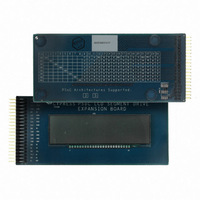
KIT DEV PSOC3 LCD SEGMENT EXPAN
Manufacturer
Cypress Semiconductor Corp
Series
PSOC™ 3r
Specifications of CY8CKIT-029
Main Purpose
Displays, LCD Display
Embedded
Yes, MCU, 32-Bit
Primary Attributes
128 addressable segments
Secondary Attributes
CD contains sample projects
Description/function
Evaluation Kit
Interface Type
USB
Backlighting
No Backlighting
Data Bus Width
8 bit, 16 bit, 32 bit
Maximum Operating Temperature
+ 50 C
Minimum Operating Temperature
0 C
Number Of Segments
7, 14
Operating Voltage
2.5 V to 5.5 V
Pixel Format
8 x 16
Product
Display Modules
Software
Software Included
Touch Panel
No Touch Panel
For Use With/related Products
PSoC 3
Lead Free Status / RoHS Status
Lead free / RoHS Compliant
Utilized Ic / Part
-
Lead Free Status / Rohs Status
Lead free / RoHS Compliant
Other names
428-2993


5.1
5.1.1
5.1.2
5.1.3
5.1.4
CY8CKIT-029 PSoC LCD Segment Drive Expansion Board Kit Guide, Doc. # 001-55415 Rev. *B
5.
Example Projects
Example Project 1: LCD_Seg_Example1_Battery_Meter
This example project demonstrates the battery charge indicator along with the 14-segment display of
the LCD glass by implementing a battery meter. The battery meter is used to graphically display the
battery charge level; the 14-segment display is used to relay messages related to the battery charge
(full, medium, and low).
Project Description
The potentiometer on the DVK is used to increase and decrease the battery meter on segment LCD.
The four segments (S2, S3, S4, S5, refer
5V) to define the switching on/off of the battery meter. This is accomplished by the Delta-Sigma ADC
count values of PSoC Creator. Based on the battery meter, 'Full', 'Medium', and 'Low' are displayed
on the 14-segment LCD display.
Figure 5-1. Battery Meter Firmware Flowchart
Running the Example Project
Follow the steps described in
device with the Batter Meter example project
Hardware Connections
Refer
Verifying Output
Vary the VR (potentiometer) and note the status changes displayed on the LCD.
Hardware Connections on page 12
Programming PSoC 3 Device on page 9
for details on hardware connections.
Figure
4-3) have four voltage levels (1.25, 2.50, 3.75 and
to program the PSoC 3
21
[+] Feedback
Related parts for CY8CKIT-029
Image
Part Number
Description
Manufacturer
Datasheet
Request
R

Part Number:
Description:
KIT DEV FOR PSOC3/5
Manufacturer:
Cypress Semiconductor Corp
Datasheet:

Part Number:
Description:
PSoC1/3/5 Development Kit
Manufacturer:
Cypress Semiconductor Corp
Datasheet:

Part Number:
Description:
KIT DEV PSOC PROC MODULE CY8C38
Manufacturer:
Cypress Semiconductor Corp

Part Number:
Description:
KIT DEV PSOC PROC MODULE CY8C29
Manufacturer:
Cypress Semiconductor Corp

Part Number:
Description:
KIT DEV PSOC ANALOG VOLTMETER
Manufacturer:
Cypress Semiconductor Corp
Datasheet:

Part Number:
Description:
KIT DEV PSOC5 FIRST TOUCH
Manufacturer:
Cypress Semiconductor Corp
Datasheet:

Part Number:
Description:
KIT DEV PSOC3 FIRSTTOUCH STARTER
Manufacturer:
Cypress Semiconductor Corp
Datasheet:
Part Number:
Description:
KIT DEV PROC MODULE PSOC5
Manufacturer:
Cypress Semiconductor Corp
Datasheet:

Part Number:
Description:
KIT PSOC CY8C28 FAMILY PROCESSOR
Manufacturer:
Cypress Semiconductor Corp
Datasheet:

Part Number:
Description:
KIT PSOC MINIPROG3 PROGRAM DEBUG
Manufacturer:
Cypress Semiconductor Corp
Datasheet:

Part Number:
Description:
KIT EVAL POWERLINE HIGH VOLT
Manufacturer:
Cypress Semiconductor Corp
Datasheet:

Part Number:
Description:
KIT PSOC FIRST TOUCH
Manufacturer:
Cypress Semiconductor Corp
Datasheet:

Part Number:
Description:
EVAL KIT WORLDTOUR2
Manufacturer:
Cypress Semiconductor Corp
Datasheet:

Part Number:
Description:
KIT UNIVERSAL CAPSENSE CTRLR
Manufacturer:
Cypress Semiconductor Corp
Datasheet:
