MCP3421EV Microchip Technology, MCP3421EV Datasheet
MCP3421EV
Specifications of MCP3421EV
Available stocks


Related parts for MCP3421EV

MCP3421EV Summary of contents
Page 1
... Microchip Technology Inc. MCP3421 SOT23-6 Evaluation Board User’s Guide DS51793A ...
Page 2
... PowerMate, PowerTool, REAL ICE, rfLAB, Select Mode, Total Endurance, WiperLock and ZENA are trademarks of Microchip Technology Incorporated in the U.S.A. and other countries. SQTP is a service mark of Microchip Technology Incorporated in the U.S.A. All other trademarks mentioned herein are property of their respective companies. ...
Page 3
... A.3 Board – Top Layer ....................................................................................... 25 A.4 Board – Top Metal Layer ............................................................................. 26 A.5 Board – Bottom Metal Layer ........................................................................ 27 Appendix B. Bill Of Materials (BOM) Worldwide Sales and Service .................................................................................... 30 © 2009 Microchip Technology Inc. MCP3421 SOT23-6 EVALUATION BOARD USER’S GUIDE Table of Contents DS51793A-page iii ...
Page 4
... MCP3421 SOT23-6 Evaluation Board User’s Guide NOTES: DS51793A-page iv © 2009 Microchip Technology Inc. ...
Page 5
... Appendix A. “Schematic and Layouts” – shows the schematic and layout diagrams for the MCP3421 SOT23-6 Evaluation Board. • Appendix B. “Bill Of Materials (BOM)” – lists the parts used to build the MCP3421 SOT23-6 Evaluation Board. © 2009 Microchip Technology Inc. MCP3421 SOT23-6 EVALUATION BOARD USER’S GUIDE Preface NOTICE TO CUSTOMERS ® ...
Page 6
... Optional arguments mcc18 [options] file [options] Choice of mutually exclusive errorlevel {0|1} arguments selection Replaces repeated text var_name [, var_name...] Represents code supplied by void main (void) user { ... } © 2009 Microchip Technology Inc. Examples ® IDE User’s Guide ...
Page 7
... Customers should contact their distributor, representative or field application engineer (FAE) for support. Local sales offices are also available to help customers. A listing of sales offices and locations is included in the back of this document. Technical support is available through the web site at: http://support.microchip.com © 2009 Microchip Technology Inc. Preface 2 C Interface and ...
Page 8
... MCP3421 SOT23-6 Evaluation Board User’s Guide DOCUMENT REVISION HISTORY Revision A (January 2009) • Initial Release of this Document. DS51793A-page 4 © 2009 Microchip Technology Inc. ...
Page 9
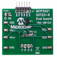
... MCP3421 device 1.2 DESCRIPTION OF THE MCP3421 SOT23-6 EVALUATION BOARD The MCP3421 SOT23-6 Evaluation Board (P/N MCP3421EV) contains a MCP3421 18-bit Delta-Sigma Analog-to-Digital Converter (ADC). The MCP3421 is an 18-bit single channel ADC device with various options. The MCP3421 SOT23-6 Evaluation Board has analog input connection pads and V can connect any sensor input signal to this evaluation board and test the ADC conversion results. The PICkit Serial Analyzer’ ...
Page 10
... MCP3421 SOT23-6 Evaluation Board User’s Guide FIGURE 1-1: Board. DS51793A-page 6 Front and Back Views of the MCP3421 SOT23-6 Evaluation © 2009 Microchip Technology Inc. ...
Page 11
... Please pay attention to the following conditions: (a) Do not apply input greater than the input range specified by the MCP3421 data sheet. (b) Apply input signal after V © 2009 Microchip Technology Inc. Quick Start Instructions from the PICkit Serial Analyzer or use your DD . You can select the V ...
Page 12
... MCP3421 SOT23-6 Evaluation Board User’s Guide USB Cable Connected between the PICkit Serial Analyzer and Personal Computer PICkit Serial Analyzer FIGURE 1-2: MCP3421 SOT23-6 Evaluation Board with the PICkit Serial Analyzer. DS51793A-page 8 Personal Computer Sensor Input Connectors MCP3421 Evaluation Board © 2009 Microchip Technology Inc. ...
Page 13
... Run the PICkit Serial PC Software. The following graphic user interface (GUI) will appear. Click the Next button and follow the instructions. FIGURE 1-3: 4. Select the I FIGURE 1-4: © 2009 Microchip Technology Inc. Quick Start Instructions PICkit Serial Analyzer Configuration Wizard Welcome Window Master option as communication mode, and click the Next button. ...
Page 14
... PICkit Serial Analyzer. FIGURE 1-6: DS51793A-page 10 Step 2 - I2C Communication Speed Window bus data rate up to 3.4 MHz, but the Step 3 - Device Pullups Window bus data rate © 2009 Microchip Technology Inc. ...
Page 15
... Case 2: When you use your own V You can also provide your own V test point on the board. In this case, make sure the JP1 jumper is disconnected. FIGURE 1-7: © 2009 Microchip Technology Inc. Quick Start Instructions voltage of the MCP3421 SOT23-6 Evaluation Board and click the DD ...
Page 16
... Click the OK button. You have made all of the PICkit Serial Analyzer configura- tion set-ups. You are now ready to program the MCP3421 SOT23-6 Evaluation Board using the PICkit Serial Analyzer. FIGURE 1-8: DS51793A-page 12 Configuration Wizard - Finishing Step. © 2009 Microchip Technology Inc. ...
Page 17
... MCP3421 SOT23-6 Evaluation Board, a script file is needed. The following procedure shows how to create script files and how to use them. • Select Communication -----> Script ---> Script Builder FIGURE 1-9: © 2009 Microchip Technology Inc. Quick Start Instructions Creating a Script File with Script Builder. DS51793A-page 13 ...
Page 18
... Choose the box and right . click the mouse button for options available. 3. Make sure the listed parameters in “Script Detail” are in the exact order as shown here. FIGURE 1-10: Modifying Parameters in the Script Builder Window. DS51793A-page Scripts” column. © 2009 Microchip Technology Inc. ...
Page 19
... All 6 parameters above must be listed in the same order as shown here. The parameter above with * are not modifiable. Address bits (A2, A1, A0) = (0,0,0) for this evaluation board. See the MCP3421 Data Sheet for more information on address bit selection. © 2009 Microchip Technology Inc. Quick Start Instructions * * ------> ...
Page 20
... Address Byte Configuration Byte Note that the “9C” in the configuration byte selects the following options: - Conversion Mode: Continuous Conversion - Bit Resolution: 18 bits - Gain Selection: 1x FIGURE 1-11: Script File Example for the I DS51793A-page 16 (9C Write Command. © 2009 Microchip Technology Inc. ...
Page 21
... LED goes OFF immediately after executing the write command. Zoom-in Write Command with Address bits 2 FIGURE 1-12 Write Command Waveforms for the MCP3421. © 2009 Microchip Technology Inc. Quick Start Instructions 2 C Write Command to the Zoom-in Configuration Bits DS51793A-page 17 ...
Page 22
... A1, A0) = (0,0,0) for the MCP3421 in this evaluation board. See the MCP3421 Data Sheet for more information on address bit selection. DS51793A-page ------> This means there is one byte for address ------> Address byte with W/R bit = 1101-0001 * ------> 5 bytes to read * © 2009 Microchip Technology Inc. ...
Page 23
... Serial Analyzer from your computer and re-check the parameter values including the order of parameters under the “Script Detail” column. Try again until the “Busy” LED goes OFF immediately after executing the read command. © 2009 Microchip Technology Inc. Quick Start Instructions Address Byte Requesting 5 Bytes Script File Sample to Read Conversion Data ...
Page 24
... Ch.1. The reading indicates the measured value is 1.0307V. See Figure 1-15 for waveforms. DS51793A-page 20 Reading Conversion Data 5th Byte: Repeated Byte for Configuration byte (note that RDY bit returned to “1” after 4th byte) 4th byte: Configuration Byte (note that RDYbit is “0”) PGA © 2009 Microchip Technology Inc. ...
Page 25
... After the RDY bit is read out at the 4th byte, the RDY bit becomes “1” in the 5th byte (repeated byte). This means the device is now in the process of a new conversion and the latest conversion result is not ready yet. © 2009 Microchip Technology Inc. Quick Start Instructions Zoom-in ...
Page 26
... MCP3421 SOT23-6 Evaluation Board User’s Guide NOTES: DS51793A-page 22 © 2009 Microchip Technology Inc. ...
Page 27
... This appendix contains the following schematics and layouts for the MCP3421 SOT23-6 Evaluation Board: • Board – Schematic • Board – Top Layer • Board – Top Metal Layer • Board – Bottom Layer © 2009 Microchip Technology Inc. MCP3421 SOT23-6 EVALUATION BOARD USER’S GUIDE DS51793A-page 23 ...
Page 28
... MCP3421 SOT23-6 Evaluation Board User’s Guide A.2 BOARD – SCHEMATIC DS51793A-page 24 © 2009 Microchip Technology Inc. ...
Page 29
... A.3 BOARD – TOP LAYER © 2009 Microchip Technology Inc. Schematic and Layouts DS51793A-page 25 ...
Page 30
... MCP3421 SOT23-6 Evaluation Board User’s Guide A.4 BOARD – TOP METAL LAYER DS51793A-page 26 © 2009 Microchip Technology Inc. ...
Page 31
... A.5 BOARD – BOTTOM METAL LAYER © 2009 Microchip Technology Inc. Schematic and Layouts DS51793A-page 27 ...
Page 32
... MCP3421 SOT23-6 Evaluation Board User’s Guide NOTES: DS51793A-page 28 © 2009 Microchip Technology Inc. ...
Page 33
... D1 LED RED ORANGE CLEAR 0805 SMD 1 J1 CONN HEADER 6POS .100 R/A TIN 1 PCB RoHS Compliant Bare PCB, MCP3421EV 2 R1,R3 RES 4.99K OHM 1/8W 1% 0805 SMD 2 R2,R4 DO NOT POPULATE 1 R5 RES 470 OHM 1/8W 5% 0805 SMD Panasonic - ECG 1 U1 ...
Page 34
... Fax: 886-3-572-6459 Taiwan - Kaohsiung Tel: 886-7-536-4818 Fax: 886-7-536-4803 Taiwan - Taipei Tel: 886-2-2500-6610 Fax: 886-2-2508-0102 Thailand - Bangkok Tel: 66-2-694-1351 Fax: 66-2-694-1350 © 2009 Microchip Technology Inc. EUROPE Austria - Wels Tel: 43-7242-2244-39 Fax: 43-7242-2244-393 Denmark - Copenhagen Tel: 45-4450-2828 Fax: 45-4485-2829 France - Paris Tel: 33-1-69-53-63-20 ...