MCP355XDV-MS1 Microchip Technology, MCP355XDV-MS1 Datasheet - Page 21
MCP355XDV-MS1
Manufacturer Part Number
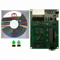
MCP355XDV-MS1
Description
BOARD DEV SENSOR APP MCP355X
Manufacturer
Microchip Technology
Datasheets
1.MCP3553-ESN.pdf
(36 pages)
2.MCP355XDV-MS1.pdf
(36 pages)
3.MCP3551DM-PCTL.pdf
(30 pages)
Specifications of MCP355XDV-MS1
Number Of Adc's
1
Number Of Bits
22
Data Interface
Serial
Inputs Per Adc
1 Differential
Input Range
±0.3 V
Voltage Supply Source
Single Supply
Operating Temperature
-40°C ~ 125°C
Utilized Ic / Part
MCP355x
Processor To Be Evaluated
MCP355x
Interface Type
RS-232, USB
Lead Free Status / RoHS Status
Not applicable / Not applicable
Lead Free Status / RoHS Status
Lead free / RoHS Compliant, Not applicable / Not applicable
Available stocks
Company
Part Number
Manufacturer
Quantity
Price
Company:

Part Number:
MCP355XDV-MS1
Manufacturer:
MICROCHIP
Quantity:
12 000


5.5
It is required that the microcontroller SPI port be config-
ured to clock out data on the falling edge of clock and
latch data in on the rising edge. Figure 5-6 depicts the
operation shown in SPI mode 1,1, which requires that
the SCK from the MCU idles in the High state, while
Figure 5-7 shows the similar case of SPI Mode 0,0,
where the clock idles in the Low state. The waveforms
in the figures are examples of an MCU operating the
SPI port in 8-bit mode, and the MCP3550/1/3 devices
do not require data in 8-bit groups.
FIGURE 5-6:
FIGURE 5-7:
© 2007 Microchip Technology Inc.
SDO/RDY
Receive
Buffer
MCU
SCK
CS
Using The MCP3550/1/3 with
Microcontroller (MCU) SPI Ports
Data stored into MCU receive
register after transmission of
first byte
DR
SDO/RDY
Receive
DR
Buffer
OH OL 21 20 19 18 17
MCU
SCK
O O
H L
CS
21 20 19 18 17
Data stored into MCU receive
register after transmission of
first byte
OL OH 21 20 19 18 17 16
SPI Communication – Mode 1,1.
SPI Communication – Mode 0,0.
D
R
O O
H L
21 20 19 18 17
16
Data stored into MCU receive
register after transmission of
second byte
16
15 14 13 12 11 10 9
15
16
14 13 12 11 10 9
Data stored into MCU receive
register after transmission of
second byte
15 14 13 12 11 10 9
15 14 13 12 11 10 9
In SPI mode 1,1, data is read using only 24 clocks or
three byte transfers. The data ready bit must be read
by testing the SDO/RDY line prior to a falling edge of
the clock.
In SPI mode 0,0, data is read using 25 clocks or four
byte transfers. Please note that the data ready bit is
included in the transfer as the first bit in this mode.
8
Data stored into MCU receive
register after transmission of
third byte
8
7
8
7
6
8
6 5 4 3 2
5
Data stored into MCU receive
register after transmission of
third byte
7
4
7 6 5 4 3 2 1
6
3 2
5
1
4
1
MCP3550/1/3
3 2
0
Data stored into MCU receive
register after transmission of
fourth byte
0
1
0
0
DS21950D-page 21
Related parts for MCP355XDV-MS1
Image
Part Number
Description
Manufacturer
Datasheet
Request
R

Part Number:
Description:
Manufacturer:
Microchip Technology Inc.
Datasheet:
Part Number:
Description:
Manufacturer:
Microchip Technology Inc.
Datasheet:
Part Number:
Description:
Manufacturer:
Microchip Technology Inc.
Datasheet:
Part Number:
Description:
Manufacturer:
Microchip Technology Inc.
Datasheet:
Part Number:
Description:
Manufacturer:
Microchip Technology Inc.
Datasheet:
Part Number:
Description:
Manufacturer:
Microchip Technology Inc.
Datasheet:
Part Number:
Description:
Manufacturer:
Microchip Technology Inc.
Datasheet:
Part Number:
Description:
Manufacturer:
Microchip Technology Inc.
Datasheet: