MCP355XDV-MS1 Microchip Technology, MCP355XDV-MS1 Datasheet - Page 23
MCP355XDV-MS1
Manufacturer Part Number
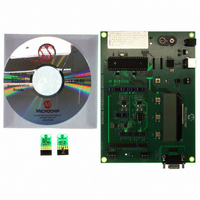
MCP355XDV-MS1
Description
BOARD DEV SENSOR APP MCP355X
Manufacturer
Microchip Technology
Datasheets
1.MCP3553-ESN.pdf
(36 pages)
2.MCP355XDV-MS1.pdf
(36 pages)
3.MCP3551DM-PCTL.pdf
(30 pages)
Specifications of MCP355XDV-MS1
Number Of Adc's
1
Number Of Bits
22
Data Interface
Serial
Inputs Per Adc
1 Differential
Input Range
±0.3 V
Voltage Supply Source
Single Supply
Operating Temperature
-40°C ~ 125°C
Utilized Ic / Part
MCP355x
Processor To Be Evaluated
MCP355x
Interface Type
RS-232, USB
Lead Free Status / RoHS Status
Not applicable / Not applicable
Lead Free Status / RoHS Status
Lead free / RoHS Compliant, Not applicable / Not applicable
Available stocks
Company
Part Number
Manufacturer
Quantity
Price
Company:

Part Number:
MCP355XDV-MS1
Manufacturer:
MICROCHIP
Quantity:
12 000


5.3
If a rising edge of Chip Select (CS) occurs during t
a subsequent conversion will not take place and the
device will enter low-power Shutdown mode after
t
Conversion mode. This operation is demonstrated in
Figure
same conversion that detected a rising edge, as in
Figure
must be read during sleep mode, with CSN low, and will
be lost as soon as the part enters in shutdown mode
(with a rising edge of CSN). After the final data bit has
been clocked out on the 25th clock, the SDO/RDY pin
will go active-high.
5.3.1
At every falling edge of CS during the internal
conversion, the state of the internal conversion is
latched on the SDO/RDY pin to give ready or busy
information. A High state means the device is currently
performing an internal conversion and data cannot be
clocked out. A Low state means the device has finished
its conversion and the data is ready for retrieval on the
falling edge of SCK. This operation is demonstrated in
Figure
Single Conversion mode with the first rising edge of
CS.
FIGURE 5-4:
Conversion Mode.
© 2009 Microchip Technology Inc.
CONV
SDO/RDY
Note:
Int. Osc
CS
5-2. Note that a falling edge of CS during the
5-2, will not initiate a new conversion. The data
5-4. Note that the device has been put into
completes. This is referred to as Single
Single Conversion Mode
READY FUNCTION OF SDO/RDY
PIN, SINGLE CONVERSION MODE
The Ready state is latched on each falling
edge of CS and will not dynamically
update if CS is held low. CS must be
toggled high through low.
t
CONV
RDY Functionality in Single
Hi-Z
CONV
,
5.4
If no rising edge of CS occurs during any given
conversion per
will take place and the contents of the previous conver-
sion will be overwritten. This operation is demonstrated
in
to be clocked out, the output buffer is not refreshed until
all 24 bits have been clocked. A complete read must
occur in order to read the next conversion in this mode.
The subsequent conversion data to be read will then be
the most recent conversion. The conversion time is
fixed and cannot be shortened by the rising edge of CS.
This rising edge will place the part in Shutdown mode
and all conversion data will be lost.
The transfer of data from the SINC filter to the output
buffer is demonstrated in
conversion data is not clocked out of the device, it will
be lost and replaced by the new conversion. When the
device is in Continuous Conversion mode, the most
recent conversion data is always present at the output
register for data retrieval.
FIGURE 5-5:
Conversion Mode Data.
If a conversion is in process, it cannot be terminated
with the rising edge of CS. SDO/RDY must first
transition to a Low state, which will indicate the end of
conversion.
SCK & SDO/RDY
Figure
Int. Osc
CS
Continuous Conversion Mode
5-5. Once conversion output data has started
t
Figure
CONV
Conversion B data is clocked
out of the device here.
MCP3550/1/3
A
Most Current Continuous
5-3, a subsequent conversion
Figure
t
CONV
B
5-5. If the previous
DS21950E-page 23
t
CONV
C
Related parts for MCP355XDV-MS1
Image
Part Number
Description
Manufacturer
Datasheet
Request
R

Part Number:
Description:
Manufacturer:
Microchip Technology Inc.
Datasheet:
Part Number:
Description:
Manufacturer:
Microchip Technology Inc.
Datasheet:
Part Number:
Description:
Manufacturer:
Microchip Technology Inc.
Datasheet:
Part Number:
Description:
Manufacturer:
Microchip Technology Inc.
Datasheet:
Part Number:
Description:
Manufacturer:
Microchip Technology Inc.
Datasheet:
Part Number:
Description:
Manufacturer:
Microchip Technology Inc.
Datasheet:
Part Number:
Description:
Manufacturer:
Microchip Technology Inc.
Datasheet:
Part Number:
Description:
Manufacturer:
Microchip Technology Inc.
Datasheet: