MCP3901EV-MCU16 Microchip Technology, MCP3901EV-MCU16 Datasheet - Page 18
MCP3901EV-MCU16
Manufacturer Part Number
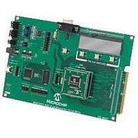
MCP3901EV-MCU16
Description
BOARD EVAL FOR 2CH ADC MCP3901
Manufacturer
Microchip Technology
Datasheets
1.MCP3901A0-ISS.pdf
(60 pages)
2.MCP3901A0-ISS.pdf
(30 pages)
3.MCP3901EV-MCU16.pdf
(38 pages)
4.MCP3901EV-MCU16.pdf
(38 pages)
Specifications of MCP3901EV-MCU16
Number Of Adc's
2
Number Of Bits
24
Data Interface
SPI™
Inputs Per Adc
1 Differential
Input Range
±1 V
Voltage Supply Source
Analog and Digital
Operating Temperature
-40°C ~ 85°C
Utilized Ic / Part
MCP3901
Silicon Manufacturer
Microchip
Application Sub Type
ADC
Kit Application Type
Data Converter
Silicon Core Number
MCP3901, PIC24F, PIC24H, DsPIC33, PIC18F86J55
Kit Contents
Board
Lead Free Status / RoHS Status
Lead free / RoHS Compliant


MCP3901 ADC Evaluation Board for 16-Bit MCUs User’s Guide
2.3
DS51845B-page 18
UART COMMUNICATION PROTOCOL
The MCU uses the UART to send and receive data to the PC. The TX and RX interrupts
are not used simultaneously in this firmware example, but it is possible to do so, if the
user requires it.
As soon as the buffer is filled with data from the ADC, the SPI interrupt is disabled, and
the TX interrupt is enabled. There are more types of data to be sent from the MCU to
the PC. The first to be sent is the data stored in the buffers. Before being sent, each
number is translated to ASCII characters that represent the number stored in the buffer.
The start of the buffer data transmissions is acknowledged by transmitting the
character: “!”.
The numbers in the current buffer are comma delimited, and each row ends with the
characters “0x0D”. After 512 rows, the buffer data transmission is complete, which is
signaled by sending out the character “D”.
Next, the data regarding the MCP3901 configuration and sampling speed is sent out.
After a total of 35 characters are sent, the MCP3901 configuration data is fully trans-
mitted, which is signaled by sending the character “;” to the PC. This character also
signals that the result of an FFT computation will be sent out next.
In the last UART TX interrupt, the TX interrupt is disabled and the RX interrupt is
enabled. Through the RX interrupt, the MCU will receive the configuration for the
MCP3901 desired by the user. The protocol is simple. The first character received must
be “D” from configuration data. Following this character will be the values of 6 registers:
PHASE, GAIN, CONFIGH, CONFIGL, STATUS, PPREG8. The first 5 registers can
hold values from 0 to 255, so they are made up of a maximum 3 characters. If the equiv-
alent number is less than 100, the first character will be the space character (“ ”), not
zero. The PREG8 register is a 16-bit register inside the MCU that controls the fre-
quency of the clock signal from OC1, which controls the sampling speed of the
MCP3901. Since it is a 16-bit register, the number of characters that create the correct
value is 5.
2010 Microchip Technology Inc.
Related parts for MCP3901EV-MCU16
Image
Part Number
Description
Manufacturer
Datasheet
Request
R

Part Number:
Description:
Manufacturer:
Microchip Technology Inc.
Datasheet:
Part Number:
Description:
Manufacturer:
Microchip Technology Inc.
Datasheet:
Part Number:
Description:
Manufacturer:
Microchip Technology Inc.
Datasheet:
Part Number:
Description:
Manufacturer:
Microchip Technology Inc.
Datasheet:
Part Number:
Description:
Manufacturer:
Microchip Technology Inc.
Datasheet:
Part Number:
Description:
Manufacturer:
Microchip Technology Inc.
Datasheet:
Part Number:
Description:
Manufacturer:
Microchip Technology Inc.
Datasheet:
Part Number:
Description:
Manufacturer:
Microchip Technology Inc.
Datasheet: