EVAL-AD7731EBZ Analog Devices Inc, EVAL-AD7731EBZ Datasheet - Page 2
EVAL-AD7731EBZ
Manufacturer Part Number
EVAL-AD7731EBZ
Description
BOARD EVALUATION FOR AD7731
Manufacturer
Analog Devices Inc
Datasheets
1.AD7731BRUZ.pdf
(44 pages)
2.EVAL-AD7731EBZ.pdf
(11 pages)
3.EVAL-AD7731EBZ.pdf
(3 pages)
4.EVAL-AD7731EBZ.pdf
(44 pages)
Specifications of EVAL-AD7731EBZ
Number Of Adc's
1
Number Of Bits
24
Sampling Rate (per Second)
6.4k
Data Interface
Serial
Inputs Per Adc
3 Differential
Input Range
±1.28 V
Power (typ) @ Conditions
67.5mW @ 6.4kSPS
Voltage Supply Source
Analog and Digital
Operating Temperature
-40°C ~ 85°C
Utilized Ic / Part
AD7731
Lead Free Status / RoHS Status
Lead free / RoHS Compliant


achieve the best from these decoupling components, they
have to be placed as close as possible to the device, ideally
right up against the device. All logic chips should be
decoupled with 0.1µF disc ceramic capacitors to DGND.
In systems where a common supply voltage is used to drive
both the AV
mended that the system’s AV
should have the recommended analog supply decoupling
capacitors between the AV
AGND and the recommended digital supply decoupling
capacitor between the DV
DGND.
POWER SUPPLIES
There is no specific power sequence required for the
AD7731, either the AV
first. While the latch-up performance of the AD7731 is very
good, it is important that power is applied to the AD7731
before signals at REF IN, AIN or the logic input pins in
order to avoid latch-up caused by excessive current. If this
is not possible, then the current which flows in any of these
pins should be limited to less than 30mA per pin and less
than 100mA cumulative. If separate supplies are used for
the AD7731 and the system digital circuitry, then the
DD
and DV
DD
DD
of the AD7731, it is recom-
DD
or the DV
DD
pin of the AD7731 and
DD
pin of the AD7731 and
supply is used. This supply
DD
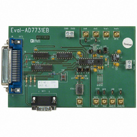
Figure 1. Eval-AD7731EB Component Side Artwork.
supply can come up
- 2 -
AD7731 should be powered up first. If it is not possible to
guarantee this, then current limiting resistors should be
placed in series with the logic inputs to again limit the
current to less than 30mA per pin and less than 100mA
total.
EVALUATING THE AD7731 PERFORMANCE
Figures 1 and 2 show a recommended layout for achieving
optimum performance from the AD7731. Figure 3 shows a
silkscreen for this layout. Details on this board are outlined
in the evaluation board application note for the AD7731.
Noise levels in the signals applied to the AD7731 may also
affect performance of the part. The AD7731 allows a
technique for evaluating the true performance of the part,
independent of the analog input signal. This scheme should
be used after a calibration has been performed on the part.
The performance obtained from the layout shown in figures
1 and 2 is outlined in Tables 1 to IV on the AD7731 data
sheet.
A full evaluation board package including a fully as-
sembled and tested evaluation board, documentation,
software for controlling the board over the printer port of a
PC and software for analyzing the AD7731’s performance
on the PC is available from Analog Devices. The evaluation
board order number is EVAL-AD7731EB.
Related parts for EVAL-AD7731EBZ
Image
Part Number
Description
Manufacturer
Datasheet
Request
R


Part Number:
Description:
BOARD EVAL FOR SI270X-A
Manufacturer:
Silicon Laboratories Inc
Datasheet:

Part Number:
Description:
BUCK CONV REF DESIGN KIT IP1201
Manufacturer:
International Rectifier
Datasheet:
Part Number:
Description:
BOARD DEMO SYNC DUAL BUCK CNVTER
Manufacturer:
International Rectifier
Datasheet:
Part Number:
Description:
BOARD DEMO SYNC BUCK CONVETER
Manufacturer:
International Rectifier
Datasheet:

Part Number:
Description:
EVALBOARD/EB Omnidirectional microphone - Analog
Manufacturer:
Analog Devices
Datasheet:
Part Number:
Description:
EVALBOARD/EB Omnidirectional microphone - Analog
Manufacturer:
Analog Devices
Datasheet:


Part Number:
Description:
BOARD EVAL LED DRIVER LT3756
Manufacturer:
Linear Technology
Datasheet:

Part Number:
Description:
BOARD EVAL FOR AD7741/7742
Manufacturer:
Analog Devices Inc
Datasheet:

Part Number:
Description:
±1.7g Dual-Axis IMEMS Accelerometer Evaluation Board
Manufacturer:
Analog Devices Inc
Datasheet:

Part Number:
Description:
IC MULTIPLIER ANALOG 8-SOIC T/R
Manufacturer:
Analog Devices Inc
Datasheet:

Part Number:
Description:
IC ANALOG MULTIPLIER 8-DIP
Manufacturer:
Analog Devices Inc
Datasheet:
Part Number:
Description:
IC ANALOG MULTIPLIER 8-SOIC
Manufacturer:
Analog Devices Inc
Datasheet:
Part Number:
Description:
IC ANALOG MULTIPLIER 8-DIP
Manufacturer:
Analog Devices Inc
Datasheet: