STEVAL-CCA007V1 STMicroelectronics, STEVAL-CCA007V1 Datasheet - Page 24
STEVAL-CCA007V1
Manufacturer Part Number
STEVAL-CCA007V1
Description
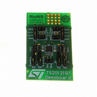
BOARD EVAL BASED ON TS2012IQT
Manufacturer
STMicroelectronics
Specifications of STEVAL-CCA007V1
Design Resources
STEVAL-CCA007V1 Gerber Files STEVAL-CCA007V1 Schematic STEVAL-CCA007V1 Bill of Material
Amplifier Type
Class D
Output Type
2-Channel (Stereo)
Max Output Power X Channels @ Load
2.8W x 2 @ 4 Ohm
Voltage - Supply
2.5 V ~ 5.5 V
Operating Temperature
-40°C ~ 85°C
Board Type
Fully Populated
Utilized Ic / Part
TS2012
Description/function
Audio Amplifiers
Operating Supply Voltage
2.5 V to 5.5 V
Output Power
2.2 W
Product
Audio Modules
Lead Free Status / RoHS Status
Lead free / RoHS Compliant
For Use With/related Products
TS2012
Other names
497-8258


Application information
4.6
Note:
4.7
Note:
4.8
4.9
24/30
Wake-up time (t
When the standby is released to set the device ON, there is a delay of 1ms typically. The
TS2012 has an internal digital delay that mutes the outputs and releases them after this
time in order to avoid any pop noise.
The gain increases smoothly (see
and G0 pin
Shutdown time
When the standby command is set, the time required to set the output stage considered into
high impedance and to put the internal circuitry in shutdown mode, is typically 1ms. This
time is used to decrease the gain and avoid any pop noise during shutdown.
The gain decreases smoothly until the outputs are muted (see
Consumption in shutdown mode
Between the shutdown pin and GND there is an internal 300kΩ (+-/20%) resistor. This
resistor forces the TS2012 to be in shutdown when the shutdown input is left floating.
However, this resistor also introduces additional shutdown power consumption if the
shutdown pin voltage is not 0V.
With a 0.4V shutdown voltage pin for example, you must add 0.4V/300kΩ=1.3µA in typical
(0.4V/240kΩ=1.66µA in maximum for each shutdown pin) to the standby current specified in
Table 5
standby pins.
Single-ended input configuration
It is possible to use the TS2012 in a single-ended input configuration. However, input
coupling capacitors are mandatory in this configuration. The schematic diagram in
shows a typical single-ended input application.
to
Table
(Section
7. Of course, this current will be provided by the external control device for
4.2).
wu
)
Figure
44) from the mute to the gain selected by the G1
Figure
44).
Figure 45
TS2012
Related parts for STEVAL-CCA007V1
Image
Part Number
Description
Manufacturer
Datasheet
Request
R

Part Number:
Description:
EVAL BOARD CC DRVR HI DENSE LEDS
Manufacturer:
STMicroelectronics
Datasheet:

Part Number:
Description:
EVAL BOARD CC DRVR HI DENSE LEDS
Manufacturer:
STMicroelectronics
Datasheet:

Part Number:
Description:
BATTERY CHARGER CELL PHONE
Manufacturer:
STMicroelectronics
Datasheet:

Part Number:
Description:
BOARD EVAL FOR MEMS SENSORS
Manufacturer:
STMicroelectronics
Datasheet:

Part Number:
Description:
KIT DEV STARTER ST10F276Z5
Manufacturer:
STMicroelectronics
Datasheet:

Part Number:
Description:
BOARD EVAL UPS 450W VOUT=220V
Manufacturer:
STMicroelectronics
Datasheet:

Part Number:
Description:
BOARD STLM75/STDS75/ST72F651
Manufacturer:
STMicroelectronics
Datasheet:

Part Number:
Description:
EVAL BOARD ENERGY METER MONO
Manufacturer:
STMicroelectronics
Datasheet:

Part Number:
Description:
EVAL BOARD ENERGY METER MONO
Manufacturer:
STMicroelectronics
Datasheet:

Part Number:
Description:
EVAL BOARD ENERGY METER MONO
Manufacturer:
STMicroelectronics
Datasheet:

Part Number:
Description:
STMicroelectronics [RIPPLE-CARRY BINARY COUNTER/DIVIDERS]
Manufacturer:
STMicroelectronics
Datasheet:
Part Number:
Description:
STMicroelectronics [LIQUID-CRYSTAL DISPLAY DRIVERS]
Manufacturer:
STMicroelectronics
Datasheet:
Part Number:
Description:
BOARD EVAL FOR MEMS SENSORS
Manufacturer:
STMicroelectronics
Datasheet: