DEMOTS2007Q STMicroelectronics, DEMOTS2007Q Datasheet - Page 23
DEMOTS2007Q
Manufacturer Part Number
DEMOTS2007Q
Description
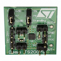
BOARD DEMO FOR TS2007IQT
Manufacturer
STMicroelectronics
Datasheet
1.TS2007IQT.pdf
(29 pages)
Specifications of DEMOTS2007Q
Amplifier Type
Class D
Output Type
1-Channel (Mono)
Max Output Power X Channels @ Load
2.8W x 1 @ 4 Ohm
Voltage - Supply
2.4 V ~ 5.5 V
Operating Temperature
-40°C ~ 85°C
Board Type
Fully Populated
Utilized Ic / Part
TS2007
Product
Audio Modules
Lead Free Status / RoHS Status
Lead free / RoHS Compliant
Other names
497-6360
Available stocks
Company
Part Number
Manufacturer
Quantity
Price


TS2007
4.5
4.6
Note:
So, for a desired cut-off frequency F
with F
The input impedance Z
is also a tolerance around the typical value (see
tolerance, you can also calculate tolerance of the F
●
●
Decoupling of the circuit
A power supply capacitor, referred to as C
The TS2007 has a typical switching frequency of 280kHz and output fall and rise time about
5ns. Due to these very fast transients, careful decoupling is mandatory.
A 1µF ceramic capacitor is enough, but it must be located very close to the TS2007 in order
to avoid any extra parasitic inductance created by a long track wire. Parasitic loop
inductance, in relation with di/dt, introduces overvoltage that decreases the global efficiency
of the device and may cause, if this parasitic inductance is too high, a TS2007 breakdown.
In addition, even if a ceramic capacitor has an adequate high frequency ESR value, its
current capability is also important. A 0603 size is a good compromise, particularly when a
4Ω load is used.
Another important parameter is the rated voltage of the capacitor. A 1µF/6.3V capacitor
used at 5V, loses about 50% of its value. With a power supply voltage of 5V, the decoupling
value, instead of 1µF, could be reduced to 0.5µF. As C
THD+N in the medium to high frequency region, this capacitor variation becomes decisive.
In addition, less decoupling means higher overshoots which can be problematic if they reach
the power supply AMR value (6V).
Wake-up time (t
When the standby is released to set the device ON, there is a wait of 5ms typically. The
TS2007 has an internal digital delay that mutes the outputs and releases them after this
time in order to avoid any pop noise.
The gain increases smoothly (see
pin
(Section
F
F
CLmax
CLmin
CL
in Hz, Z
=
=
4.2).
0.915
1.103
in
in Ω and C
⋅
⋅
F
F
CL
in
CL
wu
is for the whole power supply voltage range, typically 75k
)
in
in F.
Figure
F
C
CL
CL
in
=
we can calculate C
=
--------------------------------------------- -
2
------------------------------------------- -
2
49) from the mute to the gain selected by the GS
S,
⋅
⋅
is needed to correctly bypass the TS2007.
π
π
⋅
⋅
Z
1
1
Table 5
Z
in
in
CL
⋅
⋅
F
:
C
S
CL
in
has particular influence on the
to
in
Table
:
9). With regard to the
Application information
Ω
. There
23/29
Related parts for DEMOTS2007Q
Image
Part Number
Description
Manufacturer
Datasheet
Request
R

Part Number:
Description:
Manufacturer:
STMicroelectronics
Datasheet:

Part Number:
Description:
DEMO BOARD FOR HMC6042/HMC1041Z
Manufacturer:
Honeywell Microelectronics & Precision Sensors

Part Number:
Description:
DEMO BOARD FOR HMC1042L/HMC1041Z
Manufacturer:
Honeywell Microelectronics & Precision Sensors
Datasheet:

Part Number:
Description:
KIT DEMO 4 SENSOR CHAN RS232
Manufacturer:
VTI Technologies
Datasheet:


Part Number:
Description:
DEMO: DC Power Supply, 32 Volts, 3 Amps
Manufacturer:
Tektronix
Part Number:
Description:
DEMO: Programmable DC Power Supply, 32 Volts, 3 Amps
Manufacturer:
Tektronix
Part Number:
Description:
STMicroelectronics [RIPPLE-CARRY BINARY COUNTER/DIVIDERS]
Manufacturer:
STMicroelectronics
Datasheet:
Part Number:
Description:
STMicroelectronics [LIQUID-CRYSTAL DISPLAY DRIVERS]
Manufacturer:
STMicroelectronics
Datasheet:

Part Number:
Description:
BOARD EVAL FOR MEMS SENSORS
Manufacturer:
STMicroelectronics
Datasheet:
Part Number:
Description:
NPN TRANSISTOR POWER MODULE
Manufacturer:
STMicroelectronics
Datasheet:
Part Number:
Description:
TURBOSWITCH ULTRA-FAST HIGH VOLTAGE DIODE
Manufacturer:
STMicroelectronics
Datasheet: