DEMOTS4956J STMicroelectronics, DEMOTS4956J Datasheet
DEMOTS4956J
Specifications of DEMOTS4956J
DEMOTS4956J
Available stocks


Related parts for DEMOTS4956J


DEMOTS4956J Summary of contents
Page 1
TS4956 stereo audio amplifier system with I Introduction This application note describes the DEMO TS4956 evaluation board, designed for evaluation of the TS4956 stereo audio amplifier. The evaluation board allows the TS4956 amplifier to be driven directly via the I ...
Page 2
Contents Contents 1 Typical application schematics . . . . . . . . . . . . . . . . . . . . . . . . . . . . . . . . 3 2 ...
Page 3
AN2465 1 Typical application schematics Figure 1 on page 4 TS4956 amplifier with different configurations and different modes. The eight possible output modes are defined in Table 1. Output mode selection: Gain from -34 (by ...
Page 4
Typical application schematics Figure 1. Typical application for the TS4956 (mode Diff. input + Cin1 + 330nF Cin2 + 330nF Diff. input - SE input left Cin3 + 330nF SE input right Cin4 + ...
Page 5
AN2465 Figure 2. Typical application for the TS4956 (mode 7) SE input left Cin3 + 330nF SE input right Cin4 + 330nF 1 Vcc TS4956 Stereo MIP A1 Input Left Stereo MIN A2 Input Right Mode Select LIN Stereo B4 ...
Page 6
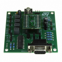
Description of the evaluation board 2 Description of the evaluation board The evaluation board is divided into two parts. One part includes a typical application for the TS4956 and provides connectors for stereo headphones with a load of 16/32Ω. The ...
Page 7
AN2465 Figure 3. Schematic diagram of the evaluation board Diff. input + JP1 Diff. input - SE input left 1 2 JP2 1 2 JP3 SE input right J1 5 GND 9 4 DTR 8 3 ...
Page 8
Description of the evaluation board Table 2. Evaluation board bill of materials Designation bypass in1 in2 in3 C out R1 R2, R3 R5, ...
Page 9
AN2465 3 Evaluation board connectors Caution: When you apply the power supply through Cn1 and Cn4, DO NOT invert the polarity because it would destroy the amplifier at U1. Connectors Cn1 Power connector for analog part of V When pins ...
Page 10
Evaluation board connectors Figure 4. TS4956 flip-chip adapter pinout Figure 5. TS4956 DEMO BOARD top view 10/15 AN2465 ...
Page 11
AN2465 4 Evaluation board layout The following schematics show the various layers and the top view of the evaluation board. Figure 6. PCB top layer Figure 8. Top view of evaluation board Evaluation board layout Figure 7. PCB bottom layer ...
Page 12
TS4956 command software 5 TS4956 command software The TS4956 command software provides a quick and easy way of driving the TS4956 audio system from a PC, and in particular of configuring the output mode and the volume. The software is ...
Page 13
AN2465 Configuring the evaluation board using the software interface There are two options that can be configured using the software interface: ● Volume: Changes the gain in the range from -34.5dB to + steps of 1.5dB. ● Mode ...
Page 14
Revision history 6 Revision history Table 3. Document revision history Date 14-Nov-2006 14/15 Revision 2 First public release. AN2465 Changes ...
Page 15
... AN2465 Information in this document is provided solely in connection with ST products. STMicroelectronics NV and its subsidiaries (“ST”) reserve the right to make changes, corrections, modifications or improvements, to this document, and the products and services described herein at any time, without notice. All ST products are sold pursuant to ST’s terms and conditions of sale. ...