NCP2809AEVB ON Semiconductor, NCP2809AEVB Datasheet
NCP2809AEVB
Manufacturer Part Number
NCP2809AEVB
Description
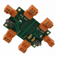
EVAL BOARD FOR NCP2809A
Manufacturer
ON Semiconductor
Series
NOCAP™r
Specifications of NCP2809AEVB
Design Resources
NCP2809AEVB BOM NCP2809AEVB Gerber Files NCP2809AEVB Schematic
Amplifier Type
Class AB
Output Type
Headphones, 2-Channel (Stereo)
Max Output Power X Channels @ Load
135mW x 2 @ 16 Ohm
Voltage - Supply
2.2 V ~ 5.5 V
Board Type
Fully Populated
Utilized Ic / Part
NCP2809
Lead Free Status / RoHS Status
Lead free / RoHS Compliant
Operating Temperature
-
Lead Free Status / Rohs Status
Lead free / RoHS Compliant
For Use With/related Products
NCP2809A
Other names
NCP2809AEVBOS
Available stocks
Company
Part Number
Manufacturer
Quantity
Price
Company:

Part Number:
NCP2809AEVB
Manufacturer:
ON Semiconductor
Quantity:
2
Equipment Needed:
The procedure described below can be used for each schematic.
This is the only test performed. You could also check the quiescent current. Place two 16
Ohm loads, no input signal, Vp set to 5V and you should measure around 1.9 mA.
12/14/2007
• DC Power Supply
• Function Generator
• Oscilloscope
• Digital Multimeter
• Set Vp = 5 V to power supply connector.
• Set two 16 Ohm loads (resistance) on the 3 points of output connector J3 and J9.
• With your Function Generator, set a sinewave signal at 1kHz and 1Vrms for the
• In case of the big output capacitors schematic, place 1 oscilloscope probe on
• In case of the capless schematic, place 2 oscilloscope probes on each output
• During the test with the capless schematic, be careful not to connect the
Test Procedure for the NCP2809A Evaluation Board
input signal. Connect it to the input connector (J2 & J8): between IN_R and
GND for the right output and once measured, between IN_L and GND for the
left one.
each output (Right & Left) and you should get a 1Vrms output signal with a
"perfect sinewave". That is to say no clipping at the minimum and maximum
of the sinewave.
(Right & Left) and the virtual ground and you should get a 1 Vrms differential
output signal with a "perfect sinewave". That is to say no clipping at the
minimum and maximum of the sinewave.
ground to the virtual ground on the output! If you do so, you'll need to
solder another NCP2809A.
- 1 -
www.onsemi.com
Related parts for NCP2809AEVB
Image
Part Number
Description
Manufacturer
Datasheet
Request
R

Part Number:
Description:
ON Semiconductor [VOLTAGE REGULATOR]
Manufacturer:
ON Semiconductor
Datasheet:
Part Number:
Description:
357-036-542-201 CARDEDGE 36POS DL .156 BLK LOPRO
Manufacturer:
ON Semiconductor
Datasheet:
Part Number:
Description:
357-036-542-201 CARDEDGE 36POS DL .156 BLK LOPRO
Manufacturer:
ON Semiconductor
Datasheet:
Part Number:
Description:
357-036-542-201 CARDEDGE 36POS DL .156 BLK LOPRO
Manufacturer:
ON Semiconductor
Datasheet:
Part Number:
Description:
357-036-542-201 CARDEDGE 36POS DL .156 BLK LOPRO
Manufacturer:
ON Semiconductor
Datasheet:
Part Number:
Description:
357-036-542-201 CARDEDGE 36POS DL .156 BLK LOPRO
Manufacturer:
ON Semiconductor
Datasheet:
Part Number:
Description:
357-036-542-201 CARDEDGE 36POS DL .156 BLK LOPRO
Manufacturer:
ON Semiconductor
Datasheet:
Part Number:
Description:
357-036-542-201 CARDEDGE 36POS DL .156 BLK LOPRO
Manufacturer:
ON Semiconductor
Datasheet:
Part Number:
Description:
357-036-542-201 CARDEDGE 36POS DL .156 BLK LOPRO
Manufacturer:
ON Semiconductor
Datasheet:
Part Number:
Description:
357-036-542-201 CARDEDGE 36POS DL .156 BLK LOPRO
Manufacturer:
ON Semiconductor
Datasheet:
Part Number:
Description:
357-036-542-201 CARDEDGE 36POS DL .156 BLK LOPRO
Manufacturer:
ON Semiconductor
Datasheet:
Part Number:
Description:
Manufacturer:
ON Semiconductor
Datasheet:
Part Number:
Description:
Manufacturer:
ON Semiconductor
Datasheet:
Part Number:
Description:
Manufacturer:
ON Semiconductor
Datasheet: