NCP2890EVB ON Semiconductor, NCP2890EVB Datasheet - Page 10
NCP2890EVB
Manufacturer Part Number
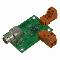
NCP2890EVB
Description
EVAL BOARD FOR NCP2890
Manufacturer
ON Semiconductor
Specifications of NCP2890EVB
Design Resources
NCP2890 Demo Board BOM NCP2890EVB Design Resources NCP2890 Demo Board Schematic
Amplifier Type
Class AB
Output Type
1-Channel (Mono)
Max Output Power X Channels @ Load
1.08W x 1 @ 8 Ohm
Voltage - Supply
2.2 V ~ 5.5 V
Board Type
Fully Populated
Utilized Ic / Part
NCP2890
Lead Free Status / RoHS Status
Lead free / RoHS Compliant
Operating Temperature
-
Lead Free Status / Rohs Status
Lead free / RoHS Compliant
For Use With/related Products
NCP2890
Other names
NCP2890EVBOS


700
600
500
400
300
200
100
0.25
0.15
0.05
0.7
0.6
0.5
0.4
0.3
0.2
0.1
0.2
0.1
0
0
0
Figure 35. Power Derating − 9−Pin Flip−Chip CSP
0
0
0
200 mm
Figure 31. Power Dissipation versus Output
P
for V
R
Figure 33. Power Dissipation versus Output
Dmax
L
= 8 W
20
p
0.2
= 5 V,
= 633 mW
2
T
50 mm
A
40
, AMBIENT TEMPERATURE (°C)
0.1
P
P
out
out
0.4
2
, OUTPUT POWER (W)
, OUTPUT POWER (W)
60
V
R
F = 1 kHz
THD + N < 0.1%
p
L
= 5 V
= 8 W
Power
V
R
F = 1 kHz
THD + N < 0.1%
Power
p
L
0.6
80
= 3 V
0.2
= 8 W
TYPICAL PERFORMANCE CHARACTERISTICS
PCB Heatsink Area
100
500 mm
0.8
120
2
0.3
NCP2890, NCV2890
1
140
http://onsemi.com
160
1.2
0.4
10
0.25
0.15
0.05
0.35
0.25
0.15
0.05
180
160
140
120
100
0.3
0.2
0.1
0.4
0.3
0.2
0.1
80
60
40
0
0
0
0
50
Figure 36. Maximum Die Temperature versus
Figure 32. Power Dissipation versus Output
Figure 34. Power Dissipation versus Output
V
p
= 2.6 V
0.05
V
p
0.1
100
V
= 3.3 V
p
0.1
= 4.2 V
R
PCB HEATSINK AREA (mm
P
P
V
L
out
out
p
PCB Heatsink Area
= 4 W
R
V
F = 1 kHz
THD + N < 0.1%
= 5 V
L
p
, OUTPUT POWER (W)
, OUTPUT POWER (W)
0.15
= 8 W
= 2.6 V
V
R
F = 1 kHz
THD + N < 0.1%
Maximum Die Temperature 150°C
150
0.2
p
L
= 3.3 V
= 8 W
Power
Power
0.2
R
200
0.3
0.25
L
= 8 W
2
0.3
)
250
0.4
0.35
300
0.4
0.5
Related parts for NCP2890EVB
Image
Part Number
Description
Manufacturer
Datasheet
Request
R

Part Number:
Description:
1w Audio Power Amplifier
Manufacturer:
ON Semiconductor
Datasheet:
Part Number:
Description:
ON Semiconductor [VOLTAGE REGULATOR]
Manufacturer:
ON Semiconductor
Datasheet:
Part Number:
Description:
357-036-542-201 CARDEDGE 36POS DL .156 BLK LOPRO
Manufacturer:
ON Semiconductor
Datasheet:
Part Number:
Description:
357-036-542-201 CARDEDGE 36POS DL .156 BLK LOPRO
Manufacturer:
ON Semiconductor
Datasheet:
Part Number:
Description:
357-036-542-201 CARDEDGE 36POS DL .156 BLK LOPRO
Manufacturer:
ON Semiconductor
Datasheet:
Part Number:
Description:
357-036-542-201 CARDEDGE 36POS DL .156 BLK LOPRO
Manufacturer:
ON Semiconductor
Datasheet:
Part Number:
Description:
357-036-542-201 CARDEDGE 36POS DL .156 BLK LOPRO
Manufacturer:
ON Semiconductor
Datasheet:
Part Number:
Description:
357-036-542-201 CARDEDGE 36POS DL .156 BLK LOPRO
Manufacturer:
ON Semiconductor
Datasheet:
Part Number:
Description:
357-036-542-201 CARDEDGE 36POS DL .156 BLK LOPRO
Manufacturer:
ON Semiconductor
Datasheet:
Part Number:
Description:
357-036-542-201 CARDEDGE 36POS DL .156 BLK LOPRO
Manufacturer:
ON Semiconductor
Datasheet:
Part Number:
Description:
357-036-542-201 CARDEDGE 36POS DL .156 BLK LOPRO
Manufacturer:
ON Semiconductor
Datasheet:
Part Number:
Description:
357-036-542-201 CARDEDGE 36POS DL .156 BLK LOPRO
Manufacturer:
ON Semiconductor
Datasheet:
Part Number:
Description:
Manufacturer:
ON Semiconductor
Datasheet:
Part Number:
Description:
Manufacturer:
ON Semiconductor
Datasheet: