NCP4894FCEVB ON Semiconductor, NCP4894FCEVB Datasheet
NCP4894FCEVB
Manufacturer Part Number
NCP4894FCEVB
Description
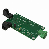
EVAL BOARD FOR NCP4894FC
Manufacturer
ON Semiconductor
Specifications of NCP4894FCEVB
Design Resources
NCP4894 Demo Board BOM NCP4894FCEVB Gerber Files NCP4894 Demo Board Schematic
Amplifier Type
Class AB
Output Type
1-Channel (Mono)
Max Output Power X Channels @ Load
1.8W x 1 @ 8 Ohm
Voltage - Supply
2.2 V ~ 5.5 V
Board Type
Fully Populated
Utilized Ic / Part
NCP4894
Lead Free Status / RoHS Status
Lead free / RoHS Compliant
Operating Temperature
-
Lead Free Status / Rohs Status
Lead free / RoHS Compliant
For Use With/related Products
NCP4894FC
Other names
NCP4894FCEVBOS


07/30/2004
Equipment Needed:
Sine Wave Generator with Differential Output
Oscilloscope
Power Supply
Digital Voltmeter
Digital Amp Meter
Signal Source Setup:
The NCP4894 requires a differential signal to drive the audio amplifier. This is done
using a waveform generator with a differential output signal. Set a sinewave differential
signal on the input connector (J2). The middle point is connected to ground while INM
and INP signals are in opposite phases. For each signal, Vin = 1 Vrms and f = 1 kHz.
NCP4894 Test:
1) Jumpers J5 & J4 should be open.
2) Set the Power Supply to 5 V with a current limit of at least 800 mA.
3) Connect Ground and Vp = 5 V to power supply connector (J1). There should be no
4) Connect an 8 Ω load (resistance) across the output connector (J3). Close J4 connector.
5) Connect oscilloscope probes on each output (OUTA & OUTB) and configure the
6) Connect the differential signal from the waveform generator to the differential input
7) Measure (OUTA-OUTB), you should see a 2 Vrms output signal with a "perfect 1
current flowing from the Vp. The measurement should be at maximum 600 nA.
The dc current measurement on Vp line should be around 2.2 mA.
scope for a differential measurement (OUTA-OUTB).
connector J2.
kHz sinewave". That is to say no clipping at the minimum and maximum of the
sinewave.
Test Procedure for the NCP4894 Evaluation Board
Related parts for NCP4894FCEVB
Image
Part Number
Description
Manufacturer
Datasheet
Request
R

Part Number:
Description:
Differential Audio Power Amplifier
Manufacturer:
ON Semiconductor
Datasheet:
Part Number:
Description:
ON Semiconductor [VOLTAGE REGULATOR]
Manufacturer:
ON Semiconductor
Datasheet:
Part Number:
Description:
357-036-542-201 CARDEDGE 36POS DL .156 BLK LOPRO
Manufacturer:
ON Semiconductor
Datasheet:
Part Number:
Description:
357-036-542-201 CARDEDGE 36POS DL .156 BLK LOPRO
Manufacturer:
ON Semiconductor
Datasheet:
Part Number:
Description:
357-036-542-201 CARDEDGE 36POS DL .156 BLK LOPRO
Manufacturer:
ON Semiconductor
Datasheet:
Part Number:
Description:
357-036-542-201 CARDEDGE 36POS DL .156 BLK LOPRO
Manufacturer:
ON Semiconductor
Datasheet:
Part Number:
Description:
357-036-542-201 CARDEDGE 36POS DL .156 BLK LOPRO
Manufacturer:
ON Semiconductor
Datasheet:
Part Number:
Description:
357-036-542-201 CARDEDGE 36POS DL .156 BLK LOPRO
Manufacturer:
ON Semiconductor
Datasheet:
Part Number:
Description:
357-036-542-201 CARDEDGE 36POS DL .156 BLK LOPRO
Manufacturer:
ON Semiconductor
Datasheet:
Part Number:
Description:
357-036-542-201 CARDEDGE 36POS DL .156 BLK LOPRO
Manufacturer:
ON Semiconductor
Datasheet:
Part Number:
Description:
357-036-542-201 CARDEDGE 36POS DL .156 BLK LOPRO
Manufacturer:
ON Semiconductor
Datasheet:
Part Number:
Description:
357-036-542-201 CARDEDGE 36POS DL .156 BLK LOPRO
Manufacturer:
ON Semiconductor
Datasheet:
Part Number:
Description:
Manufacturer:
ON Semiconductor
Datasheet:
Part Number:
Description:
Manufacturer:
ON Semiconductor
Datasheet:
NCP4894FCEVB Summary of contents
Page 1
Test Procedure for the NCP4894 Evaluation Board 07/30/2004 Equipment Needed: Sine Wave Generator with Differential Output Oscilloscope Power Supply Digital Voltmeter Digital Amp Meter Signal Source Setup: The NCP4894 requires a differential signal to drive the audio amplifier. This is ...
Page 2
Increase input amplitude of differential waveform generator to 1.4 Vrms. Verify the voltage seen by the load should be 2.8 Vrms with no clipping. Move the input from 1.4 Vrms to 1.5 Vrms, the output voltage is clipping somewhere. ...