DM300023 Microchip Technology, DM300023 Datasheet - Page 19
DM300023
Manufacturer Part Number
DM300023
Description
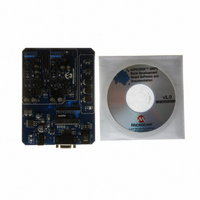
KIT DEMO DSPICDEM SMPS BUCK
Manufacturer
Microchip Technology
Series
dsPIC™r
Datasheets
1.AC164335.pdf
(286 pages)
2.DM300023.pdf
(22 pages)
3.DM300023.pdf
(18 pages)
4.DM300023.pdf
(50 pages)
5.DM300023.pdf
(16 pages)
Specifications of DM300023
Main Purpose
DC/DC, Step Down
Outputs And Type
2, Non-Isolated
Voltage - Input
7 ~ 15V
Regulator Topology
Buck
Board Type
Fully Populated
Utilized Ic / Part
dsPIC30F2020
Processor To Be Evaluated
dsPIC30F202x/1010
Interface Type
RS-232
Lead Free Status / RoHS Status
Lead free / RoHS Compliant
Current - Output
-
Voltage - Output
-
Power - Output
-
Frequency - Switching
-
Lead Free Status / Rohs Status
Lead free / RoHS Compliant
Available stocks
Company
Part Number
Manufacturer
Quantity
Price
Company:

Part Number:
DM300023
Manufacturer:
Microchip Technology
Quantity:
135
Company:
Part Number:
DM300023
Manufacturer:
MICROCHIP
Quantity:
12 000


© 2006 Microchip Technology Inc.
TABLE 2-3:
2.2.2
The dsPICDEM™ SMPS Buck Development Board has 2 switches, 3 potentiometers
and one LED for user applications. The board also has one power ON status LED and
device reset switch.
TABLE 2-4:
2.2.3
The dsPICDEM™ SMPS Buck Development Board provides seven power test points
that can be used to debug the power stage and eight PWM test points that can be used
to check the PWM signal and gate drive to buck converter 1 and 2. These test points
are described in Table 2-5 and Table 2-6, respectively.
R29, R30,
Jumper
S2, S4
Label
LED3
LED1
JP4
JP5
R35
J4
J8
S3
Switches, LEDs and Potentiometers
Test Points
Buck Converter 1 Synchronous MOSFET Drive
Buck Converter 2 Synchronous MOSFET Drive
ON: Enable Synchronous MOSFET drive for buck converter 1
OFF: Disable Synchronous MOSFET drive for buck converter 1
ON: Enable Synchronous MOSFET drive for buck converter 2
OFF: Disable Synchronous MOSFET drive for buck converter 2
Buck Converter 1 Current Sense Position Select
Jumper J4 is connected to the buck converter 1 output bulk capacitor. It allows the
user to select the current sense resistor position for different applications.
Position
1-2
2-3
Buck Converter 2 Current Sense Position Select
Jumper J8 is connected to the buck converter 2 output bulk capacitor. It allows the
user to select the current sense resistor position for different applications.
Position
1-2
2-3
applications. When momentarily depressed, the switch connects the respective
port pin to ground (Logical ‘0’).
User potentiometers connected to analog input pins (AN5, AN6 and AN7),
respectively, for user applications.
User programmable LED; programmed by writing to port pin RE9.
Power-on status LED; indicates status of 5V regulator.
Reset switch. When momentarily depressed, the switch asserts the MCLR signal
to the dsPIC
Push button switches connected to port pins RE5 and RE4, respectively, for user
JUMPER DESCRIPTIONS (CONTINUED)
PUSH BUTTONS, POTENTIOMETERS AND LEDS
Function
Current sense resistor senses output load of converter 1
Current sense resistor senses inductor current of converter 1
Function
Current sense resistor senses load current of converter 2
Current sense resistor senses inductor current of converter 2
®
DSC device for Reset.
Hardware Elements
Description
DS70181A-page 15
Related parts for DM300023
Image
Part Number
Description
Manufacturer
Datasheet
Request
R

Part Number:
Description:
Manufacturer:
Microchip Technology Inc.
Datasheet:
Part Number:
Description:
Manufacturer:
Microchip Technology Inc.
Datasheet:
Part Number:
Description:
Manufacturer:
Microchip Technology Inc.
Datasheet:
Part Number:
Description:
Manufacturer:
Microchip Technology Inc.
Datasheet:
Part Number:
Description:
Manufacturer:
Microchip Technology Inc.
Datasheet:
Part Number:
Description:
Manufacturer:
Microchip Technology Inc.
Datasheet:
Part Number:
Description:
Manufacturer:
Microchip Technology Inc.
Datasheet:
Part Number:
Description:
Manufacturer:
Microchip Technology Inc.
Datasheet: