DM300023 Microchip Technology, DM300023 Datasheet - Page 90
DM300023
Manufacturer Part Number
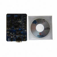
DM300023
Description
KIT DEMO DSPICDEM SMPS BUCK
Manufacturer
Microchip Technology
Series
dsPIC™r
Datasheets
1.AC164335.pdf
(286 pages)
2.DM300023.pdf
(22 pages)
3.DM300023.pdf
(18 pages)
4.DM300023.pdf
(50 pages)
5.DM300023.pdf
(16 pages)
Specifications of DM300023
Main Purpose
DC/DC, Step Down
Outputs And Type
2, Non-Isolated
Voltage - Input
7 ~ 15V
Regulator Topology
Buck
Board Type
Fully Populated
Utilized Ic / Part
dsPIC30F2020
Processor To Be Evaluated
dsPIC30F202x/1010
Interface Type
RS-232
Lead Free Status / RoHS Status
Lead free / RoHS Compliant
Current - Output
-
Voltage - Output
-
Power - Output
-
Frequency - Switching
-
Lead Free Status / Rohs Status
Lead free / RoHS Compliant
Available stocks
Company
Part Number
Manufacturer
Quantity
Price
Company:

Part Number:
DM300023
Manufacturer:
Microchip Technology
Quantity:
135
Company:
Part Number:
DM300023
Manufacturer:
MICROCHIP
Quantity:
12 000


dsPIC30F1010/202X
FIGURE 8-1:
8.1
The 16-bit timer can be placed in the Gated Time Accu-
mulation mode. This mode allows the internal T
increment the respective timer when the gate input sig-
nal (T1CK pin) is asserted high. Control bit TGATE
(T1CON<6>) must be set to enable this mode. The
timer must be enabled (TON = 1) and the timer clock
source set to internal (TCS = 0).
When the CPU goes into the Idle mode, the timer will
stop incrementing, unless TSIDL = 0. If TSIDL = 1, the
timer will resume the incrementing sequence upon
termination of the CPU Idle mode.
8.2
The input clock (F
Timer, has a prescale option of 1:1, 1:8, 1:64, and
1:256
(T1CON<5:4>). The prescaler counter is cleared when
any of the following occurs:
• a write to the TMR1 register
• clearing of the TON bit (T1CON<15>)
• device Reset such as POR
However, if the timer is disabled (TON = 0), then the
timer prescaler cannot be reset since the prescaler
clock is halted.
TMR1 is not cleared when T1CON is written. It is
cleared by writing to the TMR1 register.
DS70178C-page 88
selected
Timer Gate Operation
Timer Prescaler
T1IF
T1CK
Event Flag
OSC
by
/2 or external clock) to the 16-bit
16-BIT TIMER1 MODULE BLOCK DIAGRAM (TYPE A TIMER)
TGATE
control
0
1
Reset
Equal
bits
Comparator x 16
TCKPS<1:0>
TMR1
PR1
CY
Preliminary
Q
Q
to
Gate
Sync
CK
T
D
CY
8.3
During CPU Sleep mode, the timer will operate if:
• The timer module is enabled (TON = 1) and
• The timer clock source is selected as external
• The TSYNC bit (T1CON<2>) is asserted to a logic
When all three conditions are true, the timer will
continue to count up to the period register and be reset
to 0x0000.
When a match between the timer and the period regis-
ter occurs, an interrupt can be generated, if the
respective timer interrupt enable bit is asserted.
TGATE
(TCS = 1) and
‘0’, which defines the external clock source as
asynchronous
Timer Operation During Sleep
Mode
1 X
0 1
0 0
TON
TSYNC
© 2006 Microchip Technology Inc.
0
1
TCKPS<1:0>
1, 8, 64, 256
Prescaler
Sync
2
Related parts for DM300023
Image
Part Number
Description
Manufacturer
Datasheet
Request
R

Part Number:
Description:
Manufacturer:
Microchip Technology Inc.
Datasheet:
Part Number:
Description:
Manufacturer:
Microchip Technology Inc.
Datasheet:
Part Number:
Description:
Manufacturer:
Microchip Technology Inc.
Datasheet:
Part Number:
Description:
Manufacturer:
Microchip Technology Inc.
Datasheet:
Part Number:
Description:
Manufacturer:
Microchip Technology Inc.
Datasheet:
Part Number:
Description:
Manufacturer:
Microchip Technology Inc.
Datasheet:
Part Number:
Description:
Manufacturer:
Microchip Technology Inc.
Datasheet:
Part Number:
Description:
Manufacturer:
Microchip Technology Inc.
Datasheet: