RDK-142 Power Integrations, RDK-142 Datasheet - Page 7
RDK-142
Manufacturer Part Number
RDK-142
Description
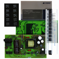
KIT REF DESIGN TOP HX FOR TOP258
Manufacturer
Power Integrations
Series
TOPSwitch®-HXr
Datasheet
1.RDK-142.pdf
(40 pages)
Specifications of RDK-142
Mfg Application Notes
TOPSwitch-HX Family Appl Note
Main Purpose
AC/DC, Primary Side
Outputs And Type
2, Non-Isolated
Power - Output
35W
Voltage - Output
5V, 12V
Current - Output
2.2A, 2A
Voltage - Input
90 ~ 265VAC
Regulator Topology
Flyback
Frequency - Switching
30kHz
Board Type
Fully Populated
Utilized Ic / Part
TOP258
Product
Accessories & Kits
Silicon Manufacturer
Power Integrations
Kit Application Type
Displays
Application Sub Type
LCD Monitor
Kit Contents
Samples, Fully Functional Reference Board And Complete Documentation
Rohs Compliant
Yes
Lead Free Status / RoHS Status
Lead free / RoHS Compliant
Other names
596-1193


07-Dec-07
RDR-142 35 W, TOP258PN Dual Output Supply
4 Circuit Description
A Flyback converter configuration built around TOP258PN is used in this power supply to
obtain two output voltages. The 5 V output can supply a load current of 2.2 A, and the
12 V output can supply a load current of 2.0 A. This power supply can operate between
90 – 264 VAC. The 5 V output is the main regulated output. This output is regulated
using a TL431 voltage reference. Some feedback is also derived from the 12 V output for
improved cross regulation.
4.1 Input EMI Filtering
The three wire AC supply is connected to the circuit using connector J1. Fuse F1
provides protection against circuit faults and effectively isolates the circuit from the AC
supply source. Thermistor RT1 limits the inrush current drawn by the circuit at start up.
Optional capacitors C1 and C2 are Y capacitors connected from the Line/Neutral to Earth
to reduce common mode EMI.
Capacitor C3 is the X capacitor and helps to reduce the differential mode EMI. Resistors
R1 and R2 discharge C3 on AC removal, preventing potential user shock. Inductor L1 is
a common-mode inductor and helps in filtering common-mode EMI from coupling back to
the AC source.
Diodes D1, D2, D3 and D4 form a bridge rectifier. The bridge rectifier rectifies the
incoming AC supply to DC, which is filtered by capacitor C4.
Diodes D1 and D3 are fast recovery type diodes. These diodes recover very quickly
when the voltage across them reverses. This reduces excitation of stray line inductance
in the AC input by reducing the subsequent high frequency turnoff snap and hence EMI.
Only 2 of the 4 diodes in the bridge need to be fast recovery type, since 2 diodes conduct
in each half cycle.
4.2 TOPSwitch-HX Primary
Resistor R3 and R4 provide line voltage sensing and provide a current to U1, which is
proportional to the DC voltage across capacitor C4. At approximately 95 V DC, the
current through these resistors exceeds the line under-voltage threshold of 25 µA, which
results in enabling of U1.
The TOPSwitch-HX regulates the output using PWM-based voltage mode control. At
high loads the controller operates at full switching frequency (66 kHz for P package
devices). The duty cycle is controlled based on the control pin current to regulate the
output voltage.
The internal current limit provides cycle-by-cycle peak current limit protection.
The
TOPSwitch-HX controller has a second current limit comparator allowing monitoring the
actual peak drain current (I
) relative to the programmed current limit I
. As soon
P
LIMITEXT
Power Integrations
Tel: +1 408 414 9200 Fax: +1 408 414 9201
Page 7 of 40
www.powerint.com
Related parts for RDK-142
Image
Part Number
Description
Manufacturer
Datasheet
Request
R

Part Number:
Description:
KIT REF DESIGN FOR LNK457D
Manufacturer:
Power Integrations
Datasheet:

Part Number:
Description:
REFERENCE DESIGN LINKSWITCH-PH
Manufacturer:
Power Integrations
Datasheet:

Part Number:
Description:
KIT REF DESIGN FOR LNK403EG
Manufacturer:
Power Integrations
Datasheet:

Part Number:
Description:
KIT REF DESIGN FOR LNK406EG
Manufacturer:
Power Integrations
Datasheet:

Part Number:
Description:
KIT REF DESIGN LINKSWITCH-CV
Manufacturer:
Power Integrations
Datasheet:

Part Number:
Description:
KIT REF DESIGN LINKSWITCH 2
Manufacturer:
Power Integrations
Datasheet:

Part Number:
Description:
Specifications: Family: Eval Boards - DC/DC & AC/DC (Off-Line) SMPS ; Series: HiperLCS™ ; Main Purpose: DC/DC, Step Down ; Outputs and Type: 1, Isolated ; Power - Output: 150W ; Voltage - Output: 24V ; Current - Output: 6.25A ; Voltage - Input:
Manufacturer:
Power Integrations, Inc.
Datasheet:

Part Number:
Description:
KIT DESIGN REF TINYSWITCH-III
Manufacturer:
Power Integrations
Datasheet:

Part Number:
Description:
KIT DESIGN REF LINKSWITCH LP
Manufacturer:
Power Integrations
Datasheet:

Part Number:
Description:
KIT REF DESIGN LED LINKSWITCH TN
Manufacturer:
Power Integrations
Datasheet:
Part Number:
Description:
KIT REF DESIGN PG LINKSWITCH-II
Manufacturer:
Power Integrations
Datasheet:
Part Number:
Description:
REFERENCE DESIGN LINKSWITCH-PL
Manufacturer:
Power Integrations
Datasheet:
Part Number:
Description:
REFERENCE DESIGN LINKSWITCH-PH
Manufacturer:
Power Integrations
Datasheet:

Part Number:
Description:
KIT REF DESIGN 36-72W MOTOR DRVR
Manufacturer:
Power Integrations
Datasheet:
Part Number:
Description:
Specifications: Manufacturer: Power Integrations ; Output Voltage: 380 VDC ; Input / Supply Voltage (Max): 264 VAC ; Input / Supply Voltage (Min): 90 VAC ; Mounting Style: Through Hole ; Output Current: 0.913 A ; Output Power: 347 W
Manufacturer:
Power Integrations, Inc.