LM5007EVAL/NOPB National Semiconductor, LM5007EVAL/NOPB Datasheet - Page 8
LM5007EVAL/NOPB
Manufacturer Part Number
LM5007EVAL/NOPB
Description
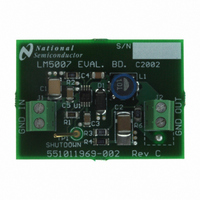
EVALUATION BOARD FOR LM5007
Manufacturer
National Semiconductor
Specifications of LM5007EVAL/NOPB
Main Purpose
DC/DC, Step Down
Outputs And Type
1, Non-Isolated
Voltage - Output
10V
Current - Output
400mA
Voltage - Input
12 ~ 75V
Regulator Topology
Buck
Board Type
Fully Populated
Utilized Ic / Part
LM5007
Lead Free Status / RoHS Status
Lead free / RoHS Compliant
Power - Output
-
Frequency - Switching
-
Lead Free Status / Rohs Status
Compliant
Other names
*LM5007EVAL
*LM5007EVAL/NOPB
LM5007EVAL
*LM5007EVAL/NOPB
LM5007EVAL
Available stocks
Company
Part Number
Manufacturer
Quantity
Price
Company:

Part Number:
LM5007EVAL/NOPB
Manufacturer:
National Semiconductor
Quantity:
135


www.national.com
The R
which disables the regulator and significantly decreases qui-
escent power dissipation. By pulling the R
Current Limit
The LM5007 contains an intelligent current limit off timer in-
tended to reduce the foldback characteristic inherent with
fixed off-time over-current protection. If the current in the Buck
switch exceeds 725mA the present cycle on time is immedi-
ately terminated (cycle by cycle current limit). Following the
termination of the cycle a non-resetable current limit off timer
is initiated. The duration of the off time is a function of the
external resistor (R
pin voltage equals zero, the current limit off time is internally
preset to 17uS. This condition occurs in short circuit operation
when a maximum amount of off time is required.
In cases of overload (not complete short circuit) the current
limit off time can be reduced as a function of the output voltage
(measured at the FB pin). Reducing the off time with smaller
overloads reduces the amount of foldback and also reduces
the initial start-up time. The current limit off time for a given
FB pin voltage and R
lowing equation:
Applications utilizing low resistance inductors and/or a low
voltage drop rectifier may require special evaluation at high
line, short circuit conditions. In this special case the preset
17uS (FB = 0V) off time may be insufficient to balance the
inductor volt*time product. Additional inductor resistance, out-
put resistance or a larger voltage drop rectifier may be nec-
essary to balance the inductor cycle volt*time product and
limit the short circuit current.
N - Channel Buck Switch and Driver
The LM5007 integrates an N-Channel Buck switch and as-
sociated floating high voltage gate driver. This gate driver
circuit works in conjunction with an external bootstrap capac-
itor and an internal high voltage diode. The bootstrap capac-
ON
Toff = 10
pin of the LM5007 also provides a shutdown function
Ton = 1.42 x 10
-5
/ (0.59 + (V
CI
) and the FB pin voltage. When the FB
CI
resistor can be calculated by the fol-
FB
-10
/ 7.22 x 10
x R
ON
/ V
ON
IN
-6
pin to below 0.7V
FIGURE 3. Shutdown Implementation
x R
CL
))
8
logic threshold activates the low power shutdown mode. The
V
100µA internal to the LM5007 plus the current in the R
sistor.
itor is charged by V
A 0.01uF ceramic capacitor connected between the BST pin
and SW pin is recommended.
During each cycle when the Buck switch turns off, the SW pin
is approximately 0V. When the SW pin voltage is low, the
bootstrap capacitor will be charged from Vcc through the in-
ternal diode. The minimum off timer, set to 300ns, ensures
that there will be a minimum interval every cycle to recharge
the bootstrap capacitor.
An external re-circulating diode from the SW pin to ground is
necessary to carry the inductor current after the internal Buck
switch turns off. This external diode must be of the Ultra-fast
or Schottky type to reduce turn-on losses and current over-
shoot. The reverse voltage rating of the re-circulating diode
must be greater than the maximum line input voltage.
Thermal Protection
Internal Thermal Shutdown circuitry is provided to protect the
integrated circuit in the event the maximum junction temper-
ature is exceeded. When thermal protection is activated,
typically at 165 degrees Celsius, the controller is forced into
a low power reset state, disabling the output driver. This fea-
ture is provided to prevent catastrophic failures from acciden-
tal device overheating.
Minimum Load Current
A minimum load current of 1 mA is required to maintain proper
operation. If the load current falls below that level, the boot-
strap capacitor may discharge during the long off-time, and
the circuit will either shutdown, or cycle on and off at a low
frequency. If the load current is expected to drop below 1 mA
in the application, the feedback resistors should be chosen
low enough in value so they provide the minimum required
current at nominal Vout.
IN
quiescent current in the shutdown mode is approximately
CC
through the internal high voltage diode.
20078307
ON
re-
Related parts for LM5007EVAL/NOPB
Image
Part Number
Description
Manufacturer
Datasheet
Request
R

Part Number:
Description:
National Semiconductor [8-Bit D/A Converter]
Manufacturer:
National Semiconductor
Datasheet:
Part Number:
Description:
National Semiconductor [Media Coprocessor]
Manufacturer:
National Semiconductor
Datasheet:
Part Number:
Description:
Digitally Controlled Tone and Volume Circuit with Stereo Audio Power Amplifier, Microphone Preamp Stage and National 3D Sound
Manufacturer:
National Semiconductor
Datasheet:
Part Number:
Description:
Digitally Controlled Tone and Volume Circuit with Stereo Audio Power Amplifier, Microphone Preamp Stage and National 3D Sound
Manufacturer:
National Semiconductor
Datasheet:
Part Number:
Description:
AC97 Rev 2 Codec with Sample Rate Conversion and National 3D Sound
Manufacturer:
National Semiconductor
Part Number:
Description:
Manufacturer:
National Semiconductor
Datasheet:
Part Number:
Description:
Manufacturer:
National Semiconductor
Datasheet:
Part Number:
Description:
General Purpose, Low Voltage, Low Power, Rail-to-Rail Output Operational Amplifiers
Manufacturer:
National Semiconductor
Datasheet:
Part Number:
Description:
8-bit 20 MSPS flash A/D converter.
Manufacturer:
National Semiconductor
Datasheet:
Part Number:
Description:
Low Noise Quad Operational Amplifier
Manufacturer:
National Semiconductor
Datasheet:
Part Number:
Description:
Quad Differential Line Receivers
Manufacturer:
National Semiconductor
Datasheet:
Part Number:
Description:
Quad High Speed Trapezoidal? Bus Transceiver
Manufacturer:
National Semiconductor
Datasheet:
Part Number:
Description:
Dual Line Receiver
Manufacturer:
National Semiconductor
Datasheet:
Part Number:
Description:
TTL to 10k ECL Level Translator with Latch
Manufacturer:
National Semiconductor
Datasheet: