LM5025EVAL National Semiconductor, LM5025EVAL Datasheet

EVALUATION BOARD FOR LM5025

LM5025EVAL

Manufacturer Part Number
LM5025EVAL
Description
EVALUATION BOARD FOR LM5025
Manufacturer
National Semiconductor
Series
PowerWise®r
Datasheets

Specifications of LM5025EVAL

Main Purpose
DC/DC, Step Down
Outputs And Type
1, Non-Isolated
Voltage - Output
3.3V
Current - Output
30A
Voltage - Input
36 ~ 72V
Regulator Topology
Buck
Frequency - Switching
230kHz
Board Type
Fully Populated
Utilized Ic / Part
LM5025
Lead Free Status / RoHS Status
Contains lead / RoHS non-compliant
Power - Output
-
Other names
*LM5025EVAL
*LM5025EVAL/NOPB
LM5025EVAL
© 2004 National Semiconductor Corporation
LM5025A Evaluation Board
Introduction
The LM5025A evaluation board is designed to provide the
design engineer with a fully functional power converter
based on the Active Clamp Forward topology to evaluate the
LM5025A controller. The evaluation board is provided in an
industry standard half-brick footprint.
The performance of the evaluation board is as follows:
• Input range: 36V to 78V (100V peak)
• Output voltage: 3.3V
• Output current: 0 to 30A
• Measured efficiency: 90.5% at 30A, 92.5% at 15A
• Frequency of operation: 230kHz
• Board size: 2.3 x 2.4 x 0.5 inches
• Load Regulation: 1%
• Line Regulation: 0.1%
• Line UVLO, Hiccup Current Limit
The printed circuit board consists of 4 layers of 3 ounce
copper on FR4 material with a total thickness of 0.050
inches. Soldermask has been omitted from some areas to
facilitate cooling. The unit is designed for continuous opera-
tion at rated load at
CFM.
Theory of Operation
Power converters based on the Forward topology offer high
efficiency and good power handling capability in applications
up to several hundred Watts. The operation of the trans-
former in a forward topology does not inherently self-reset
each power switching cycle, a mechanism to reset the trans-
former is required. The active clamp reset mechanism is
<
40˚C and a minimum airflow of 200
AN201276
National Semiconductor
Application Note 1345
Robert Bell
December 2004
presently finding extensive use in medium level power con-
verters in the 50 to 200W range.
The Forward converter is derived from the Buck topology
family, employing a single modulating power switch. The
main difference between the topologies are, the Forward
topology employs a transformer to provide input / output
ground isolation and a step down or step up function.
Each cycle, the main primary switch turns on and applies the
input voltage across the primary winding, which has 12
turns. The transformer secondary has 2 turns, leading to a
6:1 step-down of the input voltage. For an output voltage of
3.3V the required duty cycle (D) of the main switch must vary
from approximately 60% (low line) to 25% (high line). The
clamp capacitor along with the reset switch reverse biases
the transformer primary each cycle when the main switch
turns off. This reverse voltage resets the transformer. The
clamp capacitor voltage is Vin / (1-D).
The secondary rectification employs self-driven synchronous
rectification to maintain high efficiency and ease of drive.
Feedback from the output is processed by an amplifier and
reference, generating an error voltage, which is coupled
back to the primary side control through an optocoupler. The
LM5025A voltage mode controller pulse width modulates the
error signal with a ramp signal derived from the input volt-
age. Deriving the ramp signal slope from the input voltage
provides line feed-forward, which improves line transient
rejection. The LM5025A also provides a controlled delay
necessary for the reset switch.
The evaluation board can be synchronized to an external
clock with a recommended frequency range of 190 to
300KHz.
www.national.com

Related parts for LM5025EVAL

LM5025EVAL Summary of contents

Page 1

... Watts. The operation of the trans- former in a forward topology does not inherently self-reset each power switching cycle, a mechanism to reset the trans- former is required. The active clamp reset mechanism is © 2004 National Semiconductor Corporation National Semiconductor Application Note 1345 Robert Bell ...

Page 2

Theory of Operation Powering and Loading Considerations When applying power to the LM5025A evaluation board certain precautions need to be followed. A failure or mis- connection can present itself in a very alarming manner. Proper Connections When operated at low ...

Page 3

Powering Up (Continued) the wattage of the load. As you remove the connection from the shutdown pin to ground, immediately check for 3.3 volts at the output. A most common occurrence, that will prove unnerving, is when the current limit ...

Page 4

Performance Characteristics TURN-ON WAVEFORMS When applying power to the LM5025A evaluation board a certain sequence of events must occur. Soft-start capacitor values and other components allow the feedback loop to stabilize without overshoot. Figure 1 shows the output volt- age ...

Page 5

Performance Characteristics (Continued) Conditions: Input Voltage = 78VDC Output Current = 25A Trace 1: Q1 drain voltage Volts/div = 20V Horizontal Resolution = 1µs/div FIGURE 5. Conditions: Input Voltage = 48VDC Output Current = 5A Synchronous rectifier, Q3 gate Volts/div ...

Page 6

www.national.com 6 ...

Page 7

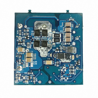
Layout and Bill of Materials The Bill of Materials is shown below and includes the manu- facturer and part number. The layers of the printed circuit board are shown in top down order. View is from the top Bill of ...

Page 8

Layout and Bill of Materials Bill of Materials (Continued) DESIGNATOR QTY R9,R10 R11 1 R12,R15,R18,R26 4 R13 1 R14 1 R23,R24 2 R27 1 R28 1 R30 ...

Page 9

PCB Layouts 20127610 9 www.national.com ...

Page 10

PCB Layouts (Continued) www.national.com 20127611 10 ...

Page 11

PCB Layouts (Continued) 20127612 11 www.national.com ...

Page 12

PCB Layouts (Continued) www.national.com 20127613 12 ...

Page 13

PCB Layouts (Continued) 20127614 13 www.national.com ...

Page 14

... BANNED SUBSTANCE COMPLIANCE National Semiconductor certifies that the products and packing materials meet the provisions of the Customer Products Stewardship Specification (CSP-9-111C2) and the Banned Substances and Materials of Interest Specification (CSP-9-111S2) and contain no ‘‘Banned Substances’’ as defined in CSP-9-111S2. ...

Related keywords