NCP3101BUCK2GEVB ON Semiconductor, NCP3101BUCK2GEVB Datasheet - Page 21
NCP3101BUCK2GEVB
Manufacturer Part Number
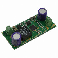
NCP3101BUCK2GEVB
Description
EVAL BOARD FOR NCP3101BUCK2G
Manufacturer
ON Semiconductor
Specifications of NCP3101BUCK2GEVB
Design Resources
NCP3101BUCK2 EVB BOM NCP3101BUCK2GEVB Gerber Files
Main Purpose
DC/DC, Step Down
Outputs And Type
1, Non-Isolated
Voltage - Output
1.5V
Current - Output
6A
Voltage - Input
5V
Regulator Topology
Buck
Board Type
Fully Populated
Utilized Ic / Part
NCP3101
Lead Free Status / RoHS Status
Lead free / RoHS Compliant
Power - Output
-
Frequency - Switching
-
Lead Free Status / Rohs Status
Lead free / RoHS Compliant
For Use With/related Products
NCP3101BUCK2G
Other names
NCP3101BUCK2GEVBOS


C
CIN
t
V
starts to switch and a second inrush current can be
calculated:
C
C
D
I
I
t
V
is dependant on the type of load that is connected to the
output. Two types of load are considered in Figure 33: a
resistive load and a stepped current load.
increase with soft start linearly which can be quantified in
Equation 54.
DELAY_TOTAL
SS
CL
OCinrush_RMS
Inrush
Current
I
5.92 A +
IN
CC
I
OUT
LOAD
OUT
Once the t
From the above equation, it is clear that the inrush current
If the load is resistive in nature, the output current will
ICin_RMS
OCinrush_RMS
Figure 33. Load Connected to the Output Stage
ESR
+
0.1 W
12 V
DELAY_TOTAL
CINESR
= Total converter output capacitance
= Total load capacitance
= Duty ratio of the load
= Applied load at the output
= RMS inrush current during start−up
= Soft start interval
= Output voltage
+
V
= Input capacitor
= Input capacitor ESR
= Total delay interval
= Input voltage
*
IN
I
120 A +
C
ICinrush_PK
D
* 0.316 *
3
OUT
) I
*
) C
CL
0.316 *
0.1
12
has expired, the buck converter
* D
t
LOAD
SS
+
5 * 0.1 W * 330 mF
CIN
V
* V
6.76 ms
IN
ESR
5 * CIN
t
OUT
DELAY_TOTAL
ESR
* C
Load
OR
IN
(eq. 51)
(eq. 52)
(eq. 53)
http://onsemi.com
21
R
V
I
I
turns on at a defined voltage level, and draws a consistent
current, then the RMS connected load current is:
I
V
V
CLR_RMS
CR_PK
OUT
I
191 mA +
OUT
OUT
OUT
OUT_TO
Alternatively, if the output has an under voltage lockout,
CLR
_RMS +
835 mA +
Figure 34. Resistive Load Current
I
1
CLKI
3
= Output resistance
= Output voltage
= RMS resistor current
= Peak resistor current
= Output current
= Output voltage
= Output voltage load turn on
*
1
3
3.3 V
10 W
+
*
R
V
OUT
OUT
3.3 V * 1.0 V
V
OUT
tss
3.3 V
Voltage
Current
Output
Output
* V
V
I
330 mA +
CR_PK
OUT
OUT_TO
+
* 1 A
V
R
3.3 V
10 W
3.3V
OUT
* I
OUT
OUT
(eq. 54)
(eq. 55)
Related parts for NCP3101BUCK2GEVB
Image
Part Number
Description
Manufacturer
Datasheet
Request
R

Part Number:
Description:
Wide Input Voltage Synchronous Buck Converter
Manufacturer:
ON Semiconductor
Datasheet:
Part Number:
Description:
ON Semiconductor [VOLTAGE REGULATOR]
Manufacturer:
ON Semiconductor
Datasheet:
Part Number:
Description:
357-036-542-201 CARDEDGE 36POS DL .156 BLK LOPRO
Manufacturer:
ON Semiconductor
Datasheet:
Part Number:
Description:
357-036-542-201 CARDEDGE 36POS DL .156 BLK LOPRO
Manufacturer:
ON Semiconductor
Datasheet:
Part Number:
Description:
357-036-542-201 CARDEDGE 36POS DL .156 BLK LOPRO
Manufacturer:
ON Semiconductor
Datasheet:
Part Number:
Description:
357-036-542-201 CARDEDGE 36POS DL .156 BLK LOPRO
Manufacturer:
ON Semiconductor
Datasheet:
Part Number:
Description:
357-036-542-201 CARDEDGE 36POS DL .156 BLK LOPRO
Manufacturer:
ON Semiconductor
Datasheet:
Part Number:
Description:
357-036-542-201 CARDEDGE 36POS DL .156 BLK LOPRO
Manufacturer:
ON Semiconductor
Datasheet:
Part Number:
Description:
357-036-542-201 CARDEDGE 36POS DL .156 BLK LOPRO
Manufacturer:
ON Semiconductor
Datasheet:
Part Number:
Description:
357-036-542-201 CARDEDGE 36POS DL .156 BLK LOPRO
Manufacturer:
ON Semiconductor
Datasheet:
Part Number:
Description:
357-036-542-201 CARDEDGE 36POS DL .156 BLK LOPRO
Manufacturer:
ON Semiconductor
Datasheet:
Part Number:
Description:
357-036-542-201 CARDEDGE 36POS DL .156 BLK LOPRO
Manufacturer:
ON Semiconductor
Datasheet:
Part Number:
Description:
Manufacturer:
ON Semiconductor
Datasheet:
Part Number:
Description:
Manufacturer:
ON Semiconductor
Datasheet: