NCP1351ADAPGEVB ON Semiconductor, NCP1351ADAPGEVB Datasheet
NCP1351ADAPGEVB
Manufacturer Part Number
NCP1351ADAPGEVB
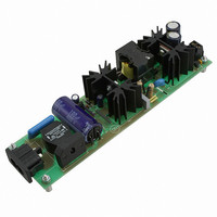
Description
EVAL BOARD FOR NCP1351ADAPG
Manufacturer
ON Semiconductor
Datasheets
1.NCP1351APG.pdf
(27 pages)
2.NCP1351ADAPGEVB.pdf
(10 pages)
3.NCP1351ADAPGEVB.pdf
(1 pages)
Specifications of NCP1351ADAPGEVB
Design Resources
NCP1351 Adapter EVB BOM NCP1351ADAPGEVB Gerber Files NCP1351 Adapter EVB Schematic
Main Purpose
AC/DC, Primary Side
Outputs And Type
1, Isolated
Power - Output
57W
Voltage - Output
19V
Current - Output
3A
Voltage - Input
90 ~ 265VAC
Regulator Topology
Flyback
Frequency - Switching
65kHz
Board Type
Fully Populated
Utilized Ic / Part
NCP1351
Lead Free Status / RoHS Status
Lead free / RoHS Compliant
Other names
NCP1351ADAPGEVBOS
8/1/2007
present on the primary side. An isolation transformer is also recommended for safer
manipulations.
Necessary Equipment:
1 Current limited 90 ÷ 265Vrms AC source (current limited to avoid board destruction in case of a defective part) or
a 380VDC source (AGILENT 6811)
1 AC Volt-Meter able to measure up to 300V AC. (KEITHLEY 2000)
1 AC Amp-Meter able to measure up to 3A AC. (KEITHLEY 2000)
1 DC Volt-Meter able to measure up to 20V DC. (KEITHLEY 2000)
1 DC Amp-Meter able to measure up to 5A DC. (KEITHLEY 2000)
1 DC Electronic Load 0 - 4A (AGILENT 6060B)
AC/DC 19 V – 3 A adapter
1. Apply 90 ÷ 230V AC over the Vin pins. Output pins (+Vout (+), Ground (-)) are left floating.
2. Measure the output voltage between pins +Vout et Ground with a volt-meter on the auto
3. Connect the electronic load between pin +Vout et Ground. Verify that the output voltage
4. If every step is going well, the board is considered to be ok.
range. The measurement should be between 18.8 and 19.2 volts.
stays above 19V. Set current 3A.
Test Procedure for the NCP1351 Adapter Evaluation Board
Be careful when manipulating the boards in operation, lethal voltages up to 400V are
Related parts for NCP1351ADAPGEVB
Image
Part Number
Description
Manufacturer
Datasheet
Request
R

Part Number:
Description:
ON Semiconductor [VOLTAGE REGULATOR]
Manufacturer:
ON Semiconductor
Datasheet:
Part Number:
Description:
357-036-542-201 CARDEDGE 36POS DL .156 BLK LOPRO
Manufacturer:
ON Semiconductor
Datasheet:
Part Number:
Description:
357-036-542-201 CARDEDGE 36POS DL .156 BLK LOPRO
Manufacturer:
ON Semiconductor
Datasheet:
Part Number:
Description:
357-036-542-201 CARDEDGE 36POS DL .156 BLK LOPRO
Manufacturer:
ON Semiconductor
Datasheet:
Part Number:
Description:
357-036-542-201 CARDEDGE 36POS DL .156 BLK LOPRO
Manufacturer:
ON Semiconductor
Datasheet:
Part Number:
Description:
357-036-542-201 CARDEDGE 36POS DL .156 BLK LOPRO
Manufacturer:
ON Semiconductor
Datasheet:
Part Number:
Description:
357-036-542-201 CARDEDGE 36POS DL .156 BLK LOPRO
Manufacturer:
ON Semiconductor
Datasheet:
Part Number:
Description:
357-036-542-201 CARDEDGE 36POS DL .156 BLK LOPRO
Manufacturer:
ON Semiconductor
Datasheet:
Part Number:
Description:
357-036-542-201 CARDEDGE 36POS DL .156 BLK LOPRO
Manufacturer:
ON Semiconductor
Datasheet:
Part Number:
Description:
357-036-542-201 CARDEDGE 36POS DL .156 BLK LOPRO
Manufacturer:
ON Semiconductor
Datasheet:
Part Number:
Description:
357-036-542-201 CARDEDGE 36POS DL .156 BLK LOPRO
Manufacturer:
ON Semiconductor
Datasheet:
Part Number:
Description:
Manufacturer:
ON Semiconductor
Datasheet:
Part Number:
Description:
Manufacturer:
ON Semiconductor
Datasheet: