NCP1081SPCGEVB ON Semiconductor, NCP1081SPCGEVB Datasheet - Page 7
NCP1081SPCGEVB
Manufacturer Part Number
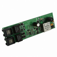
NCP1081SPCGEVB
Description
EVAL BOARD FOR NCP1081SPCG
Manufacturer
ON Semiconductor
Datasheets
1.NCP1081DER2G.pdf
(17 pages)
2.NCP1081SPCGEVB.pdf
(6 pages)
3.NCP1081SPCGEVB.pdf
(2 pages)
Specifications of NCP1081SPCGEVB
Design Resources
NCP1081SPCGEVB BOM NCP1081SPCGEVB Gerber Files NCP1081SPCGEVB Schematic
Main Purpose
Special Purpose DC/DC, Power Over Ethernet
Outputs And Type
2, Non-Isolated
Voltage - Output
12V
Current - Output
2.5A
Voltage - Input
36 ~ 57V
Regulator Topology
Buck
Frequency - Switching
250kHz
Board Type
Fully Populated
Utilized Ic / Part
NCP1081
Lead Free Status / RoHS Status
Lead free / RoHS Compliant
Power - Output
-
Lead Free Status / Rohs Status
Lead free / RoHS Compliant
For Use With/related Products
NCP1081SPCG
Other names
NCP1081SPCGEVBOS


Recommended Operating Conditions
functionality of the device outside the operating conditions described in this section is not warranted. Operating outside the
recommended operating conditions for extended periods of time may affect device reliability.
are with respect to VPORTN
4. Test done according to the IEEE 802.3af 2 Point Measurement. The minimum probe voltages measured at the PoE−PD are 1.4 V and 2.4 V,
5. This extended classification range can be used with a PSE which also uses this classification range to deliver more current than specified
6. Measured with an external Rdet of 25.5 kW between VPORTP and VPORTN
7. Measured with the 2 Point Measurement defined in the IEEE 802.3af standard with 5.4 V and 9.5 V the extreme values for V2 and V1.
8. This typical current excludes the current in the Rclass and Rdet external resistors.
Table 3. Operating Conditions
INPUT SUPPLY
SIGNATURE DETECTION
CLASSIFICATION
CLASSIFICATION INDICATOR
VPORT
Vsignature
Rsignature
Offset_current
Sleep_current
Vcl
V_mark
I_mark
dR_mark
Vreset
Iclass0
Iclass1
Iclass2
Iclass3
Iclass4
Iclass5
IDC
nCLASS_AT_i
NCLASS_AT_pd
Operating conditions define the limits for functional operation and parametric characteristics of the device. Note that the
All values concerning the DC−DC controller, VDDH, VDDL, and nCLASS_AT blocks are with respect to ARTN. All others
and the maximum probe voltages are 8.5 V and 9.5 V.
by IEEE 802.3.
– VPORTN
class
Symbol
1,2
).
Input supply voltage
Input supply voltage signature detection
range
Signature resistance (Note 4)
I_VportP + I_Rtn
I_VportP + I_Rtn
Input supply voltage classification range
Mark event voltage range (VPORTP falling)
Current consumption I(VPORTP) + I(Rdet)
in Mark Event range
Input signature during Mark Event (Note 7)
Classification Reset range
(VPORTP falling)
Class 0: Rclass 10 kW (Note 6)
Class 1: Rclass 130 ohm (Note 6)
Class 2: Rclass 69.8 ohm (Note 6)
Class 3: Rclass 44.2 ohm (Note 6)
Class 4: Rclass 30.9 ohm (Note 6)
Class 5: Rclass 22.1 ohm (Notes 5 and 6)
(for proprietary high power applications)
Internal current consumption during
classification (Note 8)
nCLASS_AT current source
NCLASS_AT pull down resistance
1,2
(unless otherwise noted).
Parameter
http://onsemi.com
7
23.75
Min.
1.4
5.4
0.5
4.3
13
17
26
36
50
13
0
−
−
−
0
9
−
1,2
, and for 13 V < VPORT < 20.5 V (with VPORT = VPORTP
Typ.
600
130
1.8
4.9
15
20
−
−
−
−
−
−
−
−
−
26.25
Max.
20.5
9.5
9.7
2.0
5.4
57
25
12
12
20
30
44
60
27
5
4
−
Units
ohm
mA
mA
mA
mA
mA
mA
mA
kW
mA
mA
kW
mA
mA
V
V
V
V
V
VPORT = VPORTP −
VPORTN
VPORTP = RTN = 1.4 V
VPORTP = RTN = 9.5 V
5.4 V ≤ VPORT ≤ 9.5 V
For information only
Iclass0 = I_VportP +
I_Rdet
Iclass1 = I_VportP +
I_Rdet
Iclass2 = I_VportP +
I_Rdet
Iclass3 = I_VportP +
I_Rdet
Iclass4 = I_VportP +
I_Rdet
Iclass5 = I_VportP +
I_Rdet
For information only
For information only
Conditions
1,2
Related parts for NCP1081SPCGEVB
Image
Part Number
Description
Manufacturer
Datasheet
Request
R

Part Number:
Description:
ON Semiconductor [VOLTAGE REGULATOR]
Manufacturer:
ON Semiconductor
Datasheet:
Part Number:
Description:
357-036-542-201 CARDEDGE 36POS DL .156 BLK LOPRO
Manufacturer:
ON Semiconductor
Datasheet:
Part Number:
Description:
357-036-542-201 CARDEDGE 36POS DL .156 BLK LOPRO
Manufacturer:
ON Semiconductor
Datasheet:
Part Number:
Description:
357-036-542-201 CARDEDGE 36POS DL .156 BLK LOPRO
Manufacturer:
ON Semiconductor
Datasheet:
Part Number:
Description:
357-036-542-201 CARDEDGE 36POS DL .156 BLK LOPRO
Manufacturer:
ON Semiconductor
Datasheet:
Part Number:
Description:
357-036-542-201 CARDEDGE 36POS DL .156 BLK LOPRO
Manufacturer:
ON Semiconductor
Datasheet:
Part Number:
Description:
357-036-542-201 CARDEDGE 36POS DL .156 BLK LOPRO
Manufacturer:
ON Semiconductor
Datasheet:
Part Number:
Description:
357-036-542-201 CARDEDGE 36POS DL .156 BLK LOPRO
Manufacturer:
ON Semiconductor
Datasheet:
Part Number:
Description:
357-036-542-201 CARDEDGE 36POS DL .156 BLK LOPRO
Manufacturer:
ON Semiconductor
Datasheet:
Part Number:
Description:
357-036-542-201 CARDEDGE 36POS DL .156 BLK LOPRO
Manufacturer:
ON Semiconductor
Datasheet:
Part Number:
Description:
357-036-542-201 CARDEDGE 36POS DL .156 BLK LOPRO
Manufacturer:
ON Semiconductor
Datasheet:
Part Number:
Description:
Manufacturer:
ON Semiconductor
Datasheet:
Part Number:
Description:
Manufacturer:
ON Semiconductor
Datasheet:
Part Number:
Description:
Manufacturer:
ON Semiconductor
Datasheet: