DAK-16A Power Integrations, DAK-16A Datasheet - Page 11
DAK-16A
Manufacturer Part Number
DAK-16A
Description
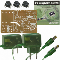
KIT DESIGN ACCELERATOR ADAPTER
Manufacturer
Power Integrations
Series
LinkSwitch®r
Specifications of DAK-16A
Main Purpose
AC/DC, Primary Side
Outputs And Type
1, Isolated
Power - Output
2.75W
Voltage - Output
5.5V
Current - Output
500mA
Voltage - Input
85 ~ 265VAC
Regulator Topology
Flyback
Frequency - Switching
42kHz
Board Type
Bare (Unpopulated)
Utilized Ic / Part
LNK500, LNK501, LNK520
Lead Free Status / RoHS Status
Not applicable / Not applicable
Other names
596-1001


17-May-04
R1 was selected to program the peak power point to be 500 mA when a transformer with
a nominal L
Power Integrations Application note, AN-35):
The closest standard 1% series value of 20.5 kΩ was selected. See AN-35 for a more
detailed explanation of clamp and feedback component selection.
C3 sets the auto-restart period and also the time the output has to reach regulation
before entering auto-restart from start-up. If a battery load is used then a value of
0.22 µF is typical. However, if the supply is required to start into a resistive load then this
should be increased to 1
regulation. The type of capacitor is not critical; either a small ceramic or electrolytic may
be used with a voltage rating of 10 V or more.
4.5 Output Stage
Diode D6 should be rated for 80% of applied reverse voltage and thermally for average
current multiplied by forward voltage at maximum ambient. Here a 1 A, 60 V Schottky
diode was used to reduce the losses and improve efficiency, although fast or ultra-fast
PN diodes are acceptable.
A snubber formed by C6 and R4 may be fitted across D6 to improve radiated EMI
performance.
Capacitor C5 should be rated for output voltage and ripple current. Depending on the
application, the designer may choose not to derate for ripple current. If the application is
battery charging of equipment such as PDAs or cell phones, the duty cycle of operation
at high ripple current is likely to be low, perhaps only 1 hour per day. In this case the
capacitor temperature can be allowed to rise significantly during charging without concern
for the overall capacitor lifetime.
Page 11 of 36
P
value was used. Initial values are selected using the expression (from
µ
F to ensure enough time during start-up to bring the output into
R1 ≅ (V
≅ (54.1 – 5.75) / 2.3 mA
≅ 21 kΩ
FB
- V
C (IDCT)
EPR-16 – LinkSwitch 2.75 W Charger/Adapter
) / I
Tel: +1 408 414 9660 Fax: +1 408 414 9760
DCT
Power Integrations
www.powerint.com
Related parts for DAK-16A
Image
Part Number
Description
Manufacturer
Datasheet
Request
R

Part Number:
Description:
KIT REF DES DPA 6.6W DC-DC CONV
Manufacturer:
Power Integrations
Datasheet:

Part Number:
Description:
KIT DESIGN ACCELERATOR POE CONV
Manufacturer:
Power Integrations
Datasheet:

Part Number:
Description:
DESIGN ACCELERATOR KIT XT SWITCH
Manufacturer:
Power Integrations
Datasheet:

Part Number:
Description:
DESIGN ACCELERATOR KIT LP SWITCH
Manufacturer:
Power Integrations
Datasheet:

Part Number:
Description:
KIT DESIGN ACC PEAKSWITCH FAMILY
Manufacturer:
Power Integrations
Datasheet:

Part Number:
Description:
KIT DESIGN ACCELERATOR ADAPTER
Manufacturer:
Power Integrations
Datasheet:

Part Number:
Description:
KIT DESIGN ACCELERATOR DC-DC
Manufacturer:
Power Integrations
Datasheet:

Part Number:
Description:
KIT DESIGN ACCELERATOR DPA SW
Manufacturer:
Power Integrations
Datasheet:

Part Number:
Description:
KIT DESIGN ACCELERATOR AC/DC PS
Manufacturer:
Power Integrations
Datasheet:

Part Number:
Description:
KIT DESIGN ACCELERATOR MODEM
Manufacturer:
Power Integrations
Datasheet: