DAK-68A Power Integrations, DAK-68A Datasheet - Page 16
DAK-68A
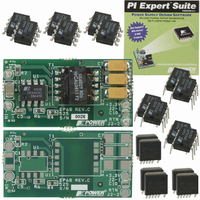
Manufacturer Part Number
DAK-68A
Description
KIT DESIGN ACCELERATOR POE CONV
Manufacturer
Power Integrations
Series
DPA-Switch®r
Specifications of DAK-68A
Main Purpose
Special Purpose DC/DC, Power Over Ethernet
Outputs And Type
1, Non-Isolated
Power - Output
6.6W
Voltage - Output
3.3V
Current - Output
2A
Voltage - Input
36 ~ 57V
Regulator Topology
Flyback
Frequency - Switching
400kHz
Board Type
Bare (Unpopulated) and Fully Populated
Utilized Ic / Part
DPA423, DPA424, DPA425
Lead Free Status / RoHS Status
Not applicable / Not applicable
Other names
596-1007


Figure 27. PoE Interface Circuit Using a Bipolar Transistor Pass-Switch and DPA424P.
Rev. S 12/07
controlled pass-switch. By adding this circuitry to the front end
of a DPA converter, a low cost and low component count PoE
powered device (PD) power supply can be implemented.
Figure 27 shows a typical PD solution.
The PoE specifi cation requires the PD to provide three
fundamental functions: discovery, classifi cation, and pass-
switch connection.
When input voltage is applied to the PD, it must present the
correct discovery signature impedance in the voltage range of
2.5 VDC to 10 VDC. This impedance is provided by R51 in
Figure 27.
The second “classifi cation” phase occurs at input voltages
15 VDC to 20 VDC. The PD must draw a specifi ed current to
identify the device class (Class 0 specifi es 0.5 mA to 4 mA).
This is again accomplished by resistor R51.
In the third phase, the bipolar pass-switch (Q51 in Figure 27)
connects the input voltage to the power supply at voltages
above approximately 30 VDC (28 V+VR52). Zener diode VR51
conducts, driving the current through resistor R52 to the base
of Q51. Resistor R53 prevents turn-on under other conditions.
Once the Power supply has started, components D51, D52,
C51 and R54 enhance the base-current drive by coupling
16
(1,2)
(4,5)
(3,6)
(7,8)
Connector
Ethernet
(RJ-45)
DPA422-426
DL4002
DL4002
DL4002
DL4002
DL4002
DL4002
DL4002
DL4002
D101
D102
D103
D104
D105
D106
D107
D108
1% 1/4 W
24.9 kΩ
TIP29C (100 V/1 A)
R51
BAV19
VR51
PoE Interface
28 V
20 kΩ
D51
R52
20 kΩ
or MMBTA06
R53
Q51
BAV19
20 Ω
1 nF
50 V
D52
C51
R54
1 μH 2.5 A
100 V
1 μF
C1
L1
649 kΩ
SMAJ
100 V
VR1
1 μF
150
1%
R1
C2
1
3
4
D
S
T1
CONTROL
X
5
8
7
6
L
DPA-Switch
174 k
R23
1%
13.3 kΩ
DPA424P
F
power from the power supply bias winding.
Once the three start up phases have been successfully
completed, the DPA-Switch is allowed to function as a forward
converter (described in Figure 25 and accompanying text).
Key Application Considerations
DPA-Switch Design Considerations
Power Table
This section provides a description of the assumptions used to
generate the power tables (Tables 1 and 3 through 6) and
explains how to use the information provided by them.
All Power tables: Tables 1 and 3 through 6
•
•
•
10 Ω
2.2 nF
R21
1%
R2
C21
MMBTS3906
U1
C
220 nF
10 Ω
Maximum output power is limited by the device internal
current limit. This is the peak output power which could
become the continuous output power, provided adequate
heat sinking is used.
Data assumes adequate heat sinking to keep the junction
temperature at or below 100 °C and worst case R
T
The use of P and G packages are recommended for device
dissipation equal to or less than 1.5 W only due to package
thermal limitation. For device dissipation above 1.5 W, use
R package.
R22
C4
Si4804
J
Si4804
Q20
Q21
= 100 °C.
Q22
10 kΩ
R23
20CJQ060
VR21
10 kΩ
D31
R22
R21
10 k
1.0 Ω
47 μF
R3
10 V
SL13
15 V
D21
C5
4
7
8
7
BAV19WS
16 μH 4 A
PC357
19WS
4.7 μF
BAV
N1T
D41
20 V
L2
D6
U2
C6
3
6
5
2
10 kΩ
R11
BAV19WS
LM431AIM3
2.2 μF
10 V
C11
VR41
6.8 V
D11
4.7 μF, 35 V
U3
100 μF 5 V
150 Ω
U2
C22-C24
R12
C41
IN4148
100 μF
10 V
D42
C31
68 nF
C13
100 nF
11 Ω
R13
C12
160 Ω
PI-3824-040706
R4
1 kΩ
R14
www.powerint.com
10 kΩ
10 kΩ
R16
R15
1%
1%
1 μF
10 V
C25
20 V, 10 mA
7.5 V, 0.4 A
DS(ON)
5 V, 2.4 A
RTN
at
Related parts for DAK-68A
Image
Part Number
Description
Manufacturer
Datasheet
Request
R

Part Number:
Description:
KIT DESIGN ACCELERATOR MODEM
Manufacturer:
Power Integrations
Datasheet:

Part Number:
Description:
KIT DESIGN ACCELERATOR SET TOP
Manufacturer:
Power Integrations
Datasheet:

Part Number:
Description:
KIT REF DES DPA 6.6W DC-DC CONV
Manufacturer:
Power Integrations
Datasheet:

Part Number:
Description:
DESIGN ACCELERATOR KIT XT SWITCH
Manufacturer:
Power Integrations
Datasheet:

Part Number:
Description:
DESIGN ACCELERATOR KIT LP SWITCH
Manufacturer:
Power Integrations
Datasheet:

Part Number:
Description:
KIT DESIGN ACC PEAKSWITCH FAMILY
Manufacturer:
Power Integrations
Datasheet:

Part Number:
Description:
KIT DESIGN ACCELERATOR ADAPTER
Manufacturer:
Power Integrations
Datasheet:

Part Number:
Description:
KIT DESIGN ACCELERATOR ADAPTER
Manufacturer:
Power Integrations
Datasheet:

Part Number:
Description:
KIT DESIGN ACCELERATOR DC-DC
Manufacturer:
Power Integrations
Datasheet:

Part Number:
Description:
KIT DESIGN ACCELERATOR DPA SW
Manufacturer:
Power Integrations
Datasheet: