IRDC3822 International Rectifier, IRDC3822 Datasheet - Page 10
IRDC3822
Manufacturer Part Number
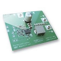
IRDC3822
Description
BOARD EVAL SYNC BUCK CONVERTER
Manufacturer
International Rectifier
Specifications of IRDC3822
Silicon Manufacturer
International Rectifier
Kit Application Type
Power Management - Voltage Regulator
Application Sub Type
Synchronous Buck Converter
Features
Programmable Soft Start, Programmable
Rohs Compliant
Yes


11/04/08
Over-Current Protection
The over-current protection is performed by
sensing current through the R
side MOSFET. This method enhances the
converter’s efficiency and reduces cost by
eliminating a current sense resistor. As shown in
figure 7, an external resistor (R
between OCSet pin and the inductor point which
sets the current limit set point.
The internal current source develops a voltage
across R
turned on, the inductor current flows through the
Q2 and results a voltage which is given by:
The critical inductor current can be calculated by
setting:
Fig. 7: Connection of over current sensing resistor
An over-current is detected if the OCSet pin goes
below ground. This trips the OCP comparator
and cycles the soft start function in hiccup mode.
The hiccup is performed by charging and
discharging the soft-start capacitor in a certain
slope rate. As shown in figure 8 a 3uA current
source is used to discharge the soft-start
capacitor.
The OCP comparator resets after every soft start
cycle. The converter stays in this mode until the
overload or short circuit is removed. The
converter will automatically recover.
V
OCSet
V
I
OCSet
SET
SET
=
(I
=
. When the low side MOSFET is
=
OCSet
I
(I
L
OCSet
(
critical
∗
R
∗
)
R
OCSet
=
OCSet
R
OCSet
)
)
−
R
−
(R
DS
(R
∗
(
on
DS(on)
DS(on)
I
OCSet
)
SET
DS(on)
∗
∗
) is connected
) I
I
L
L
)
=
of the low
--(
0
--(
3
)
2
)
The OCP circuit starts sampling current when the
low gate drive is about 3V. The OCSet pin is
internally clamped about 1.5V during on time of
high side gate to prevent false trigging, figure 9
shows the OCSet pin during one switching cycle.
As shown, there is about 150ns delay to mask
the dead time. Since this node contains switching
noises, this delay also functions as a filter.
The value of R
circuit to ensure that the over-current protection
circuit activates as expected. The IR3822 current
limit is designed primarily as disaster preventing,
and doesn't operate as a precision current
regulator.
Fig. 9: OCset pin during normal condition
Fig. 8: 3uA current source for discharging
Ch1: Inductor point, Ch3:OCSet
I
OCSet
soft-start capacitor during hiccup
*R
OCSet
SET
Deadtime
should be checked in an actual
Blanking time
IR3822MPBF
Clamp voltage
PD-60333
10
Related parts for IRDC3822
Image
Part Number
Description
Manufacturer
Datasheet
Request
R

Part Number:
Description:
SCHOTTKY RECTIFIER
Manufacturer:
International Rectifier Corp.
Datasheet:
Part Number:
Description:
SCHOTTKY RECTIFIER
Manufacturer:
International Rectifier Corp.
Datasheet:
Part Number:
Description:
SCHOTTKY RECTIFIER
Manufacturer:
International Rectifier Corp.
Datasheet:
Part Number:
Description:
SCHOTTKY RECTIFIER
Manufacturer:
International Rectifier Corp.
Datasheet:
Part Number:
Description:
SCHOTTKY RECTIFIER
Manufacturer:
International Rectifier Corp.
Datasheet:
Part Number:
Description:
SCHOTTKY RECTIFIER
Manufacturer:
International Rectifier Corp.
Datasheet:
Part Number:
Description:
SCHOTTKY RECTIFIER
Manufacturer:
International Rectifier Corp.
Datasheet:
Part Number:
Description:
SCHOTTKY RECTIFIER
Manufacturer:
International Rectifier Corp.
Datasheet:
Part Number:
Description:
SCHOTTKY RECTIFIER
Manufacturer:
International Rectifier Corp.
Datasheet:
Part Number:
Description:
SCHOTTKY RECTIFIER
Manufacturer:
International Rectifier Corp.
Datasheet:
Part Number:
Description:
SCHOTTKY RECTIFIER
Manufacturer:
International Rectifier Corp.
Datasheet:
Part Number:
Description:
SCHOTTKY RECTIFIER
Manufacturer:
International Rectifier Corp.
Datasheet:
Part Number:
Description:
SCHOTTKY RECTIFIER
Manufacturer:
International Rectifier Corp.
Datasheet:
Part Number:
Description:
SCHOTTKY RECTIFIER
Manufacturer:
International Rectifier Corp.
Datasheet:
Part Number:
Description:
SCHOTTKY RECTIFIER
Manufacturer:
International Rectifier Corp.
Datasheet: