EVL6566A-75WADP STMicroelectronics, EVL6566A-75WADP Datasheet - Page 39
EVL6566A-75WADP
Manufacturer Part Number
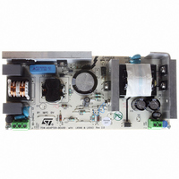
EVL6566A-75WADP
Description
BOARD EVAL FOR L6566A
Manufacturer
STMicroelectronics
Type
Power Factor Correctionr
Datasheets
1.L6566ATR.pdf
(51 pages)
2.TSM1014IDT.pdf
(10 pages)
3.L6563ATR.pdf
(39 pages)
4.EVL6566A-75WADP.pdf
(8 pages)
Specifications of EVL6566A-75WADP
Main Purpose
AC/DC, Primary and Secondary Side with PFC
Outputs And Type
1, Isolated
Power - Output
75W
Voltage - Output
19V
Current - Output
4A
Voltage - Input
90 ~ 264VAC
Frequency - Switching
65kHz
Board Type
Fully Populated
Utilized Ic / Part
L6563, L6566A, TSM1014
Input Voltage
90 V to 264 V
Output Voltage
19 V
Dimensions
78 mm x 174 mm
Product
Power Management Modules
Lead Free Status / RoHS Status
Lead free / RoHS Compliant
Regulator Topology
-
Lead Free Status / Rohs Status
Lead free / RoHS Compliant
For Use With/related Products
L6563, L6566A
Other names
497-6449
Available stocks
Company
Part Number
Manufacturer
Quantity
Price


L6566A
While the brownout protection is active the start-up generator keeps on working but, being
there no PWM activity, the Vcc voltage continuously oscillates between the start-up and the
HV generator restart thresholds, as shown in the timing diagram of
The brownout comparator is provided with current hysteresis in addition to voltage
hysteresis: an internal 15 µA current sink is ON as long as the voltage applied on the
AC_OK pin is such that the AC_FAIL signal is high. This approach provides an additional
degree of freedom: it is possible to set the ON threshold and the OFF threshold separately
by properly choosing the resistors of the external divider (see below). With just voltage
hysteresis, instead, fixing one threshold automatically fixes the other one depending on the
built-in hysteresis of the comparator.
With reference to
the ON (Vsen
Equation 13
which, solved for R
Equation 14
It is typically convenient not to use additional dividers connected to high-voltage rails
because this could make it difficult to meet no-load consumption targets envisaged by
energy-saving regulations.
use of the divider already used by the PFC control chip to sense the ac mains voltage with
just the addition of an extra tap.
The small-signal NPN Q and the capacitor C
of the rms mains voltage can be found across C
to be sensed by the AC_OK pin. It is convenient to use a level as high as possible to
minimize the effect of V
the maximum sensed voltage below 7 V to prevent Q’s emitter reverse breakdown; it would
not be destructive because the reverse current would be quite small (the resistors seen by
Figure 26. AC voltage sensing with the L6566A
L6562/A
L6561
L6563
Vsen
ON
R
H
) and OFF (Vsen
3
ON
Figure 25 on page 38
=
R
H
MULT
input voltage
Vsen
H
−
and R
Rectified
. 0
BE
485
ON
changes with temperature. However, it could be necessary to limit
L
Figure 26
, yield:
−
15
R
R
=
Q
. 1
H
L
15
⋅
078
10
OFF
⋅
10
−
6
⋅
Vsen < 7V
) thresholds of the sensed voltage:
shows a simple voltage sensing technique that makes
Vsen
−
Sensed
voltage:
6
C
, the following relationships can be established for
F
AC_OK
+
. 0
OFF
R
485
F
L
make a peak detector, so that the information
16
;
F
. Tap’s position determines the dc voltage
L6566A
Vcc
R
5
L
=
Vsen
R
H
Vsen
OFF
R
H
−
Application information
OFF
. 0
Figure 25 on page 38
. 0
45
45
−
. 0
=
45
. 0
temperature drift
Q
R
For minimum
45
L
39/51
.
Related parts for EVL6566A-75WADP
Image
Part Number
Description
Manufacturer
Datasheet
Request
R

Part Number:
Description:
BOARD DEMO FOR L6563/LL6566A
Manufacturer:
STMicroelectronics
Datasheet:

Part Number:
Description:
STMicroelectronics [RIPPLE-CARRY BINARY COUNTER/DIVIDERS]
Manufacturer:
STMicroelectronics
Datasheet:
Part Number:
Description:
STMicroelectronics [LIQUID-CRYSTAL DISPLAY DRIVERS]
Manufacturer:
STMicroelectronics
Datasheet:

Part Number:
Description:
BOARD EVAL FOR MEMS SENSORS
Manufacturer:
STMicroelectronics
Datasheet:
Part Number:
Description:
NPN TRANSISTOR POWER MODULE
Manufacturer:
STMicroelectronics
Datasheet:
Part Number:
Description:
TURBOSWITCH ULTRA-FAST HIGH VOLTAGE DIODE
Manufacturer:
STMicroelectronics
Datasheet:
Part Number:
Description:
Manufacturer:
STMicroelectronics
Datasheet:
Part Number:
Description:
DIODE / SCR MODULE
Manufacturer:
STMicroelectronics
Datasheet:
Part Number:
Description:
DIODE / SCR MODULE
Manufacturer:
STMicroelectronics
Datasheet:
Part Number:
Description:
Search -----> STE16N100
Manufacturer:
STMicroelectronics
Datasheet:
Part Number:
Description:
Search ---> STE53NA50
Manufacturer:
STMicroelectronics
Datasheet:
Part Number:
Description:
NPN Transistor Power Module
Manufacturer:
STMicroelectronics
Datasheet: