EVL6566A-75WES4 STMicroelectronics, EVL6566A-75WES4 Datasheet - Page 25
EVL6566A-75WES4
Manufacturer Part Number
EVL6566A-75WES4
Description
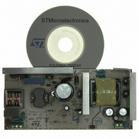
BOARD DEMO FOR L6563/LL6566A
Manufacturer
STMicroelectronics
Type
Power Factor Correctionr
Specifications of EVL6566A-75WES4
Main Purpose
AC/DC, Primary and Secondary Side with PFC
Outputs And Type
1, Isolated
Power - Output
75W
Voltage - Output
19V
Current - Output
4A
Voltage - Input
90 ~ 264VAC
Regulator Topology
Flyback
Board Type
Fully Populated
Utilized Ic / Part
L6563, L6566A, TSM1014
Input Voltage
90 V to 264 V
Output Voltage
19 V
Dimensions
78 mm x 170 mm
Product
Power Management Modules
Lead Free Status / RoHS Status
Lead free / RoHS Compliant
Frequency - Switching
-
Lead Free Status / Rohs Status
Lead free / RoHS Compliant
For Use With/related Products
L6563S, L6566A
Other names
497-8834
Available stocks
Company
Part Number
Manufacturer
Quantity
Price


L6563S
Figure 36. Voltage feedforward: squarer-divider (1/V
In this way a change of the line voltage will cause an inversely proportional change of the
half sine amplitude at the output of the multiplier (if the line voltage doubles the amplitude of
the multiplier output will be halved and vice versa) so that the current reference is adapted to
the new operating conditions with (ideally) no need for invoking the slow dynamics of the
error amplifier. Additionally, the loop gain will be constant throughout the input voltage
range, which improves significantly dynamic behavior at low line and simplifies loop design.
Actually, deriving a voltage proportional to the RMS line voltage implies a form of integration,
which has its own time constant. If it is too small the voltage generated will be affected by a
considerable amount of ripple at twice the mains frequency that will cause distortion of the
current reference (resulting in high THD and poor PF); if it is too large there will be a
considerable delay in setting the right amount of feedforward, resulting in excessive
overshoot and undershoot of the pre-regulator's output voltage in response to large line
voltage changes. Clearly a trade-off was required.
The L6563S realizes a NEW voltage feed forward that, with a technique that makes use of
just two external parts, strongly minimizes this time constant trade-off issue whichever
voltage change occurs on the mains, both surges and drops. A capacitor C
RFF, both connected from the pin VFF (#5) to ground, complete an internal peak-holding
circuit that provides a DC voltage equal to the peak of the rectified sine wave applied on pin
MULT (#3). In this way, in case of sudden line voltage rise, C
through the low impedance of the internal diode; in case of line voltage drop, an internal
“mains drop” detector enables a low impedance switch which suddenly discharges CFF
avoiding long settling time before reaching the new voltage level. The discharge of CFF is
stopped as its voltage equals the voltage on pin MULT or if the voltage on pin RUN (in case
it is connected to VFF) falls below 0.88 V, to prevent the “Brownout protection” function from
being improperly activated (see
As a result of the VFF pin functionality, an acceptably low steady-state ripple and low current
distortion can be achieved with a limited undershoot or overshoot on the pre-regulator's
output.
Doc ID 16116 Rev 4
“Section 6.7 on page
2
) block diagram and transfer characteristic
31).
FF
will be rapidly charged
Application information
FF
and a resistor
25/43
Related parts for EVL6566A-75WES4
Image
Part Number
Description
Manufacturer
Datasheet
Request
R

Part Number:
Description:
BOARD EVAL FOR L6566A
Manufacturer:
STMicroelectronics
Datasheet:

Part Number:
Description:
STMicroelectronics [RIPPLE-CARRY BINARY COUNTER/DIVIDERS]
Manufacturer:
STMicroelectronics
Datasheet:
Part Number:
Description:
STMicroelectronics [LIQUID-CRYSTAL DISPLAY DRIVERS]
Manufacturer:
STMicroelectronics
Datasheet:

Part Number:
Description:
BOARD EVAL FOR MEMS SENSORS
Manufacturer:
STMicroelectronics
Datasheet:
Part Number:
Description:
NPN TRANSISTOR POWER MODULE
Manufacturer:
STMicroelectronics
Datasheet:
Part Number:
Description:
TURBOSWITCH ULTRA-FAST HIGH VOLTAGE DIODE
Manufacturer:
STMicroelectronics
Datasheet:
Part Number:
Description:
Manufacturer:
STMicroelectronics
Datasheet:
Part Number:
Description:
DIODE / SCR MODULE
Manufacturer:
STMicroelectronics
Datasheet:
Part Number:
Description:
DIODE / SCR MODULE
Manufacturer:
STMicroelectronics
Datasheet:
Part Number:
Description:
Search -----> STE16N100
Manufacturer:
STMicroelectronics
Datasheet:
Part Number:
Description:
Search ---> STE53NA50
Manufacturer:
STMicroelectronics
Datasheet:
Part Number:
Description:
NPN Transistor Power Module
Manufacturer:
STMicroelectronics
Datasheet: