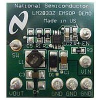
LM2833ZMYEVAL National Semiconductor, LM2833ZMYEVAL Datasheet - Page 11

LM2833ZMYEVAL
Manufacturer Part Number
LM2833ZMYEVAL
Description
BOARD EVAL LM2833 3MHZ 10MSOP
Manufacturer
National Semiconductor
Specifications of LM2833ZMYEVAL
Main Purpose
DC/DC, Step Down
Outputs And Type
1, Non-Isolated
Voltage - Output
1.2V
Current - Output
3A
Voltage - Input
3 ~ 5.5V
Regulator Topology
Buck
Frequency - Switching
3MHz
Board Type
Fully Populated
Utilized Ic / Part
LM2833
Silicon Manufacturer
National
Silicon Core Number
LM2833
Kit Application Type
Power Management - Voltage Regulator
Application Sub Type
Step Down Switching Regulator
Kit Contents
Board, Doc
Lead Free Status / RoHS Status
Lead free / RoHS Compliant
Power - Output
-
FIGURE 5. Startup Response to V
FIGURE 4. Startup Response to V
FIGURE 3. Startup Response to V
IN
with 100µs rise time
IN
with C
IN
30013260
30013262
30013261
FF
11
FREQUENCY FOLDBACK
The LM2833 uses frequency foldback to help limit switch cur-
rent and power dissipation during start-up, short-circuit and
over load conditions by sensing if the feedback voltage is be-
low 0.32V (typical). The LM2833 will reduce the switching
frequency from the nominal fixed value (1.5MHz or 3.0MHz)
down to 400kHz (LM2833X) or 800kHz (LM2833Z) when the
feedback voltage drops to 0V. See the Frequency Foldback
plot in the Typical Performance Characteristics section.
LOAD STEP RESPONSE
The LM2833 has a fixed internal loop compensation, which
results in a small-signal loop bandwidth highly related to the
output voltage level. In general, the loop bandwidth at low
voltage is larger than at high voltage due to the increased
overall loop gain. The limited bandwidth at high output voltage
may pose a challenge when loop step response is concerned.
In this case, one effective approach to improving loop step
response is to add a feed-forward capacitor (C
of 27nF to 100nF in parallel with the upper feedback resistor
(assuming the lower feedback resistor is 2kΩ), as shown in
Figure 6. The feed-forward capacitor introduces a zero-pole
pair which helps compensate the loop. The position of the
zero-pole pair is a function of the feedback resistors and ca-
pacitor:
Note the factor in parenthesis is the ratio of the output voltage
to the feedback voltage. As the output voltage gets close to
0.6V, the pole moves towards the zero, tending to cancel it
out. Consequently, adding C
response at lower output voltages.
As an example, Figure 8 shows that at the output voltage of
3.3V, a 47nF of C
from the original 23kHz as shown in Figure 7. Correspond-
ingly, the responses to a load step between 0.3A and 3A
without and with C
respectively. The higher loop bandwidth as a result of C
duces the total output excursion by more than half.
Aside from the above approach, increasing the output capac-
itance is generally also effective to reduce the excursion in
output voltage caused by a load step. This approach remains
valid for applications where the desired output voltages are
close to the feedback voltage.
FF
FF
can boost the loop bandwidth to 117kHz,
are shown in Figure 9 and Figure 10
FF
will have less effect on the step
FF
) in the range
www.national.com
FF
re-


