LM2650EVAL/NOPB National Semiconductor, LM2650EVAL/NOPB Datasheet

EVALUATION BOARD FOR LM2650X

LM2650EVAL/NOPB

Manufacturer Part Number
LM2650EVAL/NOPB
Description
EVALUATION BOARD FOR LM2650X
Manufacturer
National Semiconductor
Datasheets

Specifications of LM2650EVAL/NOPB

Main Purpose
DC/DC, Step Down
Outputs And Type
1, Non-Isolated
Voltage - Output
1.5 ~ 16V
Current - Output
3A
Voltage - Input
4.5 ~ 18V
Regulator Topology
Buck
Board Type
Fully Populated
Utilized Ic / Part
LM2650
Lead Free Status / RoHS Status
Lead free / RoHS Compliant
Power - Output
-
Frequency - Switching
-
Other names
*LM2650EVAL
*LM2650EVAL/NOPB
LM2650EVAL
© 2002 National Semiconductor Corporation
Information About the
LM2650 Evaluation Board
Rev. 1
Introduction
A printed circuit board (PCB) has been developed. This
application note contains information about the board.
General Description
The LM2650 evaluation board is provided as a tool for
developing DC/DC converters based on the LM2650 IC. It is
configured for single-output, step-down DC/DC converters.
Figure 1 is a complete schematic of the board which can
accommodate up to 28 components including the LM2650.
Table 1 is a complete list of pads for placing components.
Note: Not all applications will require the placement of all 28
components. The number of components placed depends
on the requirements of the application and the use of fea-
tures like programmable soft-start. The LM2650 evaluation
board is intended to be a reusable tool on which many
different converters meeting the requirements of many dif-
ferent applications can be built. It is not intended to demon-
strate only one application of the LM2650.
Thermal Performance
The 24-lead SO package is a molded plastic package with a
solid copper lead frame. Most of the heat generated at the
die flows through the lead frame into the 3-ounce copper
planes on the board. The board then acts as a heat sink. The
junction-to-ambient thermal resistance of the packaged IC
mounted on the board has been measured to be 38˚C/W, 37
˚C/W, and 35 ˚C/W for the dissipation of 1.0W, 1.5W, and
FIGURE 1. The LM2650 Evaluation Board Rev. 1 Schematic
AN100011
National Semiconductor
Application Note 1071
Steven Hunt
October 1997
For convenience, a sample of the LM2650 and eight other
components have been assembled: a 0.1 µF capacitor at
each of C1, C2, C6, and CB, a 0.2 µF capacitor at CVDD, a
0.01 µF capacitor at CSS, a 24.9 kΩ resistor at R2, and a 0Ω
resistor at R4. Of the eight, the first seven are common to
many applications, and the last is simply a jumper grounding
the SYNC input. When the synchronization feature is not
being used, the SYNC input should be grounded.
Example Circuits
The components contained in Tables 2, 3, and 4 can be used
to build typical application circuits. As with the design of any
DC/DC converter, the design of these involved tradeoffs
between efficiency, size, and cost. The converters detailed in
Table 2 were designed with efficiency as the number one
criteria. Those detailed in Table 4 trade slightly higher switch-
ing losses for a much smaller inductor.
2.0W respectively. These measurements were made in still
air. The junction-to-ambient thermal resistance of the pack-
aged IC alone in still air is 78˚C/W. The board is 0.063’ thick
FR-4 material.
Art
Figure 2 through Figure 4 show the PCB art work.
www.national.com
10001105

Related parts for LM2650EVAL/NOPB

LM2650EVAL/NOPB Summary of contents
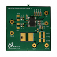
Page 1

... The board then acts as a heat sink. The junction-to-ambient thermal resistance of the packaged IC mounted on the board has been measured to be 38˚C/W, 37 ˚C/W, and 35 ˚C/W for the dissipation of 1.0W, 1.5W, and © 2002 National Semiconductor Corporation National Semiconductor Application Note 1071 Steven Hunt ...

Page 2

TABLE 1. A Complete List of Pads for Placing Components Label # U1 1 C1, C2, C3, and C10 CIN1 and CIN2 2 COUT1, COUT2, and COUT3 ...

Page 3

TABLE 2. Components for Two Typical 90 kHz Application Circuits (Continued) Sleep Resistors RSIA and RSIA = 33 kΩ, RSOA = 200 kΩ RSOA TABLE 3. Toroidal Inductors Using Cores from MICROMETALS, INC. Core # 15 µH T38 20 µH ...

Page 4

FIGURE 2. LM2650 Evaluation Board Top Silk Screen (Scale 1:1) FIGURE 3. LM2650 Evaluation Board Bottom Silk Screen (Scale 1:1) www.national.com 10001101 10001102 4 ...

Page 5

FIGURE 4. LM2650 Evaluation Board Component Side (Scale 1:1) FIGURE 5. LM2650 Evaluation Board Solder Side (Scale 1:1) 5 10001103 10001104 www.national.com ...

Page 6

... NATIONAL’S PRODUCTS ARE NOT AUTHORIZED FOR USE AS CRITICAL COMPONENTS IN LIFE SUPPORT DEVICES OR SYSTEMS WITHOUT THE EXPRESS WRITTEN APPROVAL OF THE PRESIDENT AND GENERAL COUNSEL OF NATIONAL SEMICONDUCTOR CORPORATION. As used herein: 1. Life support devices or systems are devices or systems which, (a) are intended for surgical implant ...

Related keywords