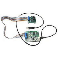
EVAL-AD5422EBZ Analog Devices Inc, EVAL-AD5422EBZ Datasheet

EVAL-AD5422EBZ
Specifications of EVAL-AD5422EBZ
Related parts for EVAL-AD5422EBZ
EVAL-AD5422EBZ Summary of contents
Page 1
... Rev. 0 Evaluation boards are only intended for device evaluation and not for production purposes. Evaluation boards are supplied “as is” and without warranties of any kind, express, implied, or statutory including, but not limited to, any implied warranty of merchantability or fitness for a particular purpose. No license is granted by implication or otherwise under any patents or other intellectual property by application or use of evaluation boards ...
Page 2
... Evaluation Board Software .............................................................. 6 REVISION HISTORY 7/09—Revision 0: Initial Version Installing the Software ..................................................................6 Using the Software ........................................................................6 Software Operation .......................................................................7 Evaluation Board Schematics and Artwork ...................................8 Ordering Information .................................................................... 11 Bill of Materials ........................................................................... 11 Ordering Guide .......................................................................... 12 ESD Caution................................................................................ 12 Rev Page ...
Page 3
... The position of Link 7 configures the board for either PC control via the USB port (default setup) or for control by an external source via J8. The link options on the evaluation board should be set for the required operating setup before using the board. The functions of the link options are described in Table 4. ...
Page 4
... Position B selects J7 as the 5 V digital circuitry power supply source. LK7 This link selects whether the AD5422 evaluation board is controlled by the PC via the USB port external source via J8. Position A selects the evaluation board to be controlled by the PC via the USB port. Position B selects the evaluation board to be controlled by an external source via J8. ...
Page 5
... AD5422 is connected to the on-board digital power supply. (LK3 must be CC pin of the AD5422 is disconnected from the on-board digital power supply. (LK3 should CC pin of the AD5422 to the power supply applied at the AV DD Rev Page EVAL-AD5422 input is SS input is SS input connector, J2. (LK18 must be DD ...
Page 6
... CD. Install the evaluation software before connecting the evaluation board to the USB port of the PC to ensure that the evaluation board is correctly recognized when connected to the PC. After the CD installation is complete, 1 ...
Page 7
... To program a voltage or current output value, type the value in either volts or milliamperes in the Enter Output Value box of the Program Voltage/Current section, and then press the Enter key. The output must first be enabled, and the output range must be selected via the Control Register section. Rev Page EVAL-AD5422 ...
Page 8
... EVAL-AD5422 EVALUATION BOARD SCHEMATICS AND ARTWORK Figure 4. Schematic of the Controller Circuitry Rev Page 08230-004 ...
Page 9
... Figure 5. Schematic of the AD5422 Circuitry Rev Page EVAL-AD5422 08230-005 ...
Page 10
... EVAL-AD5422 Figure 6. Component Placement Figure 7. Solder Side PCB Figure 8. Component Side PCB Rev Page ...
Page 11
... SMD resistor 2.2 μ Y5V ceramic capacitor 24 MHz plastic SMD crystal 10 μ (FK series) electrolytic capacitor USB mini-B connector NPN transistor, PBSS8110Z Low noise, precision operational amplifier Rev Page EVAL-AD5422 Supplier/Number Analog Devices/AD5422BREZ Analog Devices/AD7321BRUZ Analog Devices/ADG774BRQZ Analog Devices/ADP3303ARZ-3.3 Analog Devices/ADR435ARZ Cypress Semiconductor/ ...
Page 12
... EVAL-AD5422 ORDERING GUIDE Model Package Description EVAL-AD5422EBZ 1 AD5422 Evaluation Board RoHS Compliant Part. ©2009 Analog Devices, Inc. All rights reserved. Trademarks and registered trademarks are the property of their respective owners. ESD CAUTION EB08230-0-7/09(0) Rev Page ...


