CDB4398 Cirrus Logic Inc, CDB4398 Datasheet - Page 36
CDB4398
Manufacturer Part Number
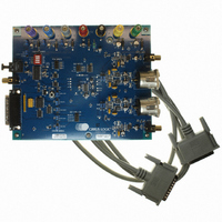
CDB4398
Description
BOARD EVAL FOR CS4398 DAC
Manufacturer
Cirrus Logic Inc
Specifications of CDB4398
Number Of Dac's
2
Number Of Bits
24
Outputs And Type
2, Differential
Sampling Rate (per Second)
192k
Data Interface
I²C, SPI™
Dac Type
Voltage
Voltage Supply Source
Analog and Digital
Operating Temperature
-10°C ~ 70°C
Utilized Ic / Part
CS4398
Description/function
Audio D/A
Operating Supply Voltage
5 V
Product
Audio Modules
For Use With/related Products
CS4398
Lead Free Status / RoHS Status
Contains lead / RoHS non-compliant
Lead Free Status / RoHS Status
Lead free / RoHS Compliant, Contains lead / RoHS non-compliant
Other names
598-1155


36
7.7.2
Notes: For best results, it is recommended that this feature be used in conjunction with the RMP_DN bit.
7.7.3
Notes: For best results, it is recommended that this feature be used in conjunction with the RMP_UP bit.
7.7.4
7.7.5
Soft Volume Ramp-up after Error (RMP_UP) Bit 5
Function:
An un-mute will be performed after executing an LRCK/MCLK ratio change or error, and after changing
the Functional Mode.
When set to 1 (default), this un-mute is effected, similar to attenuation changes, by the Soft and Zero
Cross bits in the Volume and Mixing Control register.
When set to 0, an immediate un-mute is performed in these instances.
Soft Ramp-down before Filter Mode Change (RMP_DN) Bit 4
Function:
If either the FILT_SEL or DEM bits are changed the DAC will stop conversion for a period of time to
change its filter values. This bit selects how the data is effected prior to and after the change of the filter
values.
When set to 1 (default), a mute will be performed prior to executing a filter mode change and an un-mute
will be performed after executing the filter mode change. This mute and un-mute are effected, similar to
attenuation changes, by the Soft and Zero Cross bits in the Volume and Mixing Control register.
When set to 0, an immediate mute is performed prior to executing a filter mode change.
Interpolation Filter Select (FILT_SEL) Bit 2
Function:
When set to 0 (default), the Interpolation Filter has a fast roll off.
When set to 1, the Interpolation Filter has a slow roll off.
The specifications for each filter can be found in the Analog characteristics table, and response plots can
be found in figures 20 to 43 found in the “Appendix” on page 41.
Direct DSD Conversion (DIR_DSD) Bit 0
Function:
When set to 0 (default), DSD input data is sent to the DSD processor for filtering and volume control func-
tions.
When set to 1, DSD input data is sent directly to the switched capacitor DACs for a pure DSD conversion.
In this mode, the full-scale DSD and PCM levels will not be matched (see Section 2), the dynamic range
performance may be reduced, the volume control is inactive, and the 50 kHz low pass filter is not available
(see Section 2 for filter specifications).
CS4398
DS568F1
Related parts for CDB4398
Image
Part Number
Description
Manufacturer
Datasheet
Request
R

Part Number:
Description:
Development Kit
Manufacturer:
Cirrus Logic Inc
Datasheet:
Part Number:
Description:
Development Kit
Manufacturer:
Cirrus Logic Inc
Datasheet:


Part Number:
Description:
High-efficiency PFC + Fluorescent Lamp Driver Reference Design
Manufacturer:
Cirrus Logic Inc
Datasheet:
Part Number:
Description:
Development Kit
Manufacturer:
Cirrus Logic Inc
Datasheet:
Part Number:
Description:
Development Kit
Manufacturer:
Cirrus Logic Inc
Datasheet:

Part Number:
Description:
Development Kit
Manufacturer:
Cirrus Logic Inc
Datasheet:
Part Number:
Description:
Development Kit
Manufacturer:
Cirrus Logic Inc
Datasheet:
Part Number:
Description:
Development Kit
Manufacturer:
Cirrus Logic Inc
Datasheet:
Part Number:
Description:
Development Kit
Manufacturer:
Cirrus Logic Inc
Datasheet:

Part Number:
Description:
EVALUATION BOARD FOR CS8427
Manufacturer:
Cirrus Logic Inc
Datasheet:

Part Number:
Description:
BOARD EVAL FOR CS8416 RCVR
Manufacturer:
Cirrus Logic Inc
Datasheet:

Part Number:
Description:
EVALUATION BOARD FOR CS8420
Manufacturer:
Cirrus Logic Inc
Datasheet:

Part Number:
Description:
KIT DEVELOPMENT EP9315 ARM9
Manufacturer:
Cirrus Logic Inc
Datasheet:

Part Number:
Description:
KIT DEVELOPMENT EP9302 ARM9
Manufacturer:
Cirrus Logic Inc
Datasheet: