MCP1630DM-LED2 Microchip Technology, MCP1630DM-LED2 Datasheet
MCP1630DM-LED2
Specifications of MCP1630DM-LED2
Available stocks


Related parts for MCP1630DM-LED2


MCP1630DM-LED2 Summary of contents
Page 1
... Microchip Technology Inc. Boost Mode LED Driver MCP1630 Demo Board User’s Guide DS51665B ...
Page 2
... PowerInfo, PowerMate, PowerTool, REAL ICE, rfLAB, Select Mode, Smart Serial, SmartTel, Total Endurance, UNI/O, WiperLock and ZENA are trademarks of Microchip Technology Incorporated in the U.S.A. and other countries. SQTP is a service mark of Microchip Technology Incorporated in the U.S.A. All other trademarks mentioned herein are property of their respective companies. ...
Page 3
... A.2 Board - Schematic ....................................................................................... 14 A.3 Board - Top Layer ........................................................................................ 15 A.4 Board - Top Silk Layer ................................................................................. 16 A.5 Board - Bottom Layer ................................................................................... 17 Appendix B. Bill Of Materials (BOM) ......................................................................... 19 Appendix C. Firmware Flowchart .............................................................................. 21 Worldwide Sales and Service .................................................................................... 24 © 2007 Microchip Technology Inc. DEMO BOARD USER’S GUIDE Table of Contents DS51665B-page iii ...
Page 4
... MCP1630 Boost Mode LED Driver Demo Board User’s Guide NOTES: DS51665B-page iv © 2007 Microchip Technology Inc. ...
Page 5
... Appendix B. “Bill Of Materials (BOM)” – Lists the parts used to build the MCP1630 Boost Mode LED Driver Demo Board. • Appendix C. “Firmware Flowchart” - Provides a flow chart of the firmware for the MCP1630 Boost Mode LED Driver Demo Board © 2007 Microchip Technology Inc. DEMO BOARD USER’S GUIDE Preface NOTICE TO CUSTOMERS ® ...
Page 6
... Optional arguments mcc18 [options] file [options] Choice of mutually exclusive errorlevel {0|1} arguments selection Replaces repeated text var_name [, var_name...] Represents code supplied by void main (void) user { ... } © 2007 Microchip Technology Inc. Examples ® IDE User’s Guide ...
Page 7
... Customers should contact their distributor, representative or field application engineer for support. Local sales offices are also available to help customers. A listing of sales offices and locations is included in the back of this document. Technical support is available through the web site at: http://support.microchip.com © 2007 Microchip Technology Inc. DS51665B-page 3 ...
Page 8
... Changed MCP1630 device to MCP1630V throughout document • Added additional verbiage in Section 1.1 Introduction • Updated Figure 1-1 • Updated schematic to show MPC1630V device • Changed MCP1630 device part number in BOM to MCP1630V device Revision A (May 2007) • Initial Release of this Document. DS51665B-page 4 © 2007 Microchip Technology Inc. ...
Page 9
... Optional software dimming control • Factory programmed source code provided • Switching frequency, maximum duty cycle, and MCP1630 reference voltage can be modified in firmware • Additional application functions can be provided in firmware © 2007 Microchip Technology Inc. DEMO BOARD USER’S GUIDE DS51665B-page 5 ...
Page 10
... GP4 GP1 6 GP2/ 4 GP3 5 CCP1 Reference Circuit Output Voltage Feedback FIGURE 1-1: MCP1630 Boost Mode LED Driver Demo Board Simplified Block Diagram. DS51665B-page 6 +5 MCP1630V Vdd Vref Comp - Output Driver Osc 4 Vss Clock + LED String © 2007 Microchip Technology Inc. ...
Page 11
... Microchip Inc., part # AC162039, if needed. This power supply will drive the supplied string of LEDs at 350 mA only (5W output). 2. Oscilloscope and/or multi-meter to observe waveforms and measure electrical parameters (optional). © 2007 Microchip Technology Inc. DEMO BOARD USER’S GUIDE DS51665B-page 7 ...
Page 12
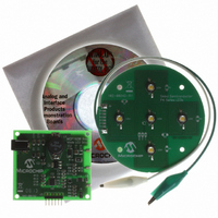
... LEDs to circuit ground. The TP2 terminal is connected to a current sensing resistor and is not at ground potential during normal operation. Damage to the circuit will occur if the TP2 terminal is connected to ground. Connect to TP1 Connector wire with 'alligator' FIGURE 2-1: DS51665B-page 8 clip LED Load Board. Connect to TP2 © 2007 Microchip Technology Inc. ...
Page 13
... MCU software. If desired, the CCP can be reconfig- ured to obtain different clock frequencies up to the 2 MHz maximum specification for the MCP1630. © 2007 Microchip Technology Inc. ), connect the multi-meter across TP1 and LED ) passes through the LED load as well as current sense ...
Page 14
... MCP1630. The reference to the MCP1630 is also disabled by clearing pin GP5. After the over-voltage event, the software provides a delay before restarting the input clock to the MCP1630 PWM generator and turning on the reference voltage. The delay reduces stress on the power supply components. DS51665B-page 10 © 2007 Microchip Technology Inc. ...
Page 15
... PIC12F683 data sheet (DS41211) for more information temperature sensor can also be used for thermal management of the LEDs. Microchip Technology, Inc. provides a range of analog and digital output temperature sensors for different application needs. The ICSP programming header (J3) on the PCB provides a convenient method to access 5V, ground, and two I/O pins ...
Page 16
... Header J3 is provided for in-circuit programming. The MCP1630 Boost Mode LED Driver Demo Board comes pre-programmed with firmware to operate the system. The PIC12F683 can be reprogrammed with the PICkit 2 Debug Express (Microchip P/N: DV164121), which is a low-cost Flash microcontroller programmer and a debugger. DS51665B-page 12 © 2007 Microchip Technology Inc. ...
Page 17
... Mode LED Driver Demo Board: • Board – Schematic • Board – Top Layer • Board – Top Silk Layer • Board – Bottom Layer © 2007 Microchip Technology Inc. MCP1630 BOOST MODE LED DRIVER DEMO BOARD USER’S GUIDE DS51665B-page 13 ...
Page 18
... MCP1630 Boost Mode LED Driver Demo Board User’s Guide A.2 BOARD - SCHEMATIC DS51665B-page 14 © 2007 Microchip Technology Inc. ...
Page 19
... A.3 BOARD - TOP LAYER © 2007 Microchip Technology Inc. DS51665B-page 15 ...
Page 20
... MCP1630 Boost Mode LED Driver Demo Board User’s Guide A.4 BOARD - TOP SILK LAYER DS51665B-page 16 © 2007 Microchip Technology Inc. ...
Page 21
... A.5 BOARD - BOTTOM LAYER © 2007 Microchip Technology Inc. DS51665B-page 17 ...
Page 22
... MCP1630 Boost Mode LED Driver Demo Board User’s Guide NOTES: DS51665B-page 18 © 2007 Microchip Technology Inc. ...
Page 23
... RES 160K OHM 1/8W 5% 0805 SMD Note 1: The components listed in this Bill of Materials are representative of the PCB assembly. The released BOM used in manufacturing uses all RoHS-compliant components. © 2007 Microchip Technology Inc. MCP1630 BOOST MODE LED DRIVER DEMO BOARD USER’S GUIDE Description ...
Page 24
... U2 MCU, 8-SOIC 1 U3 PWM Peripheral, 8-MSOP Note 1: The components listed in this Bill of Materials are representative of the PCB assembly. The released BOM used in manufacturing uses all RoHS-compliant components. © 2007 Microchip Technology Inc. Description Manufacturer — Rohm Rohm Rohm Panasonic - ECG Keystone Electronics ...
Page 25
... MCP1630 BOOST MODE LED DRIVER Appendix C. Firmware Flowchart B FIGURE C-1: Firmware Flowchart - Page 1. © 2007 Microchip Technology Inc. DEMO BOARD USER’S GUIDE Start Initialize: GP2 (for Output PWM) And GP5 (for Output V REF Internal Osc Clock to 8 MHz, TMR0 = 0 Configure Ansel & CMCON0 as Digital I/O ...
Page 26
... NO Check ADC for Overvoltage B NO Overvoltage? YES 1. Stop clock to MCP1630 2. Stop reference voltage to MCP1630 3. Initialize Delay for 25 mSec FIGURE C-2: Firmware Flowchart - Page 2. DS51665B-page 22 YES Is Delay expired? YES 1. Restart clock to MCP1630 2. Restart reference voltage to MCP1630 NO © 2007 Microchip Technology Inc. ...
Page 27
... NOTES: © 2007 Microchip Technology Inc. DS51665B-page 23 ...
Page 28
... Fax: 886-3-572-6459 Taiwan - Kaohsiung Tel: 886-7-536-4818 Fax: 886-7-536-4803 Taiwan - Taipei Tel: 886-2-2500-6610 Fax: 886-2-2508-0102 Thailand - Bangkok Tel: 66-2-694-1351 Fax: 66-2-694-1350 © 2007 Microchip Technology Inc. EUROPE Austria - Wels Tel: 43-7242-2244-39 Fax: 43-7242-2244-393 Denmark - Copenhagen Tel: 45-4450-2828 Fax: 45-4485-2829 France - Paris Tel: 33-1-69-53-63-20 ...