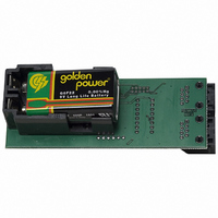
PCA9633DEMO Future Designs Inc, PCA9633DEMO Datasheet - Page 3

PCA9633DEMO
Manufacturer Part Number
PCA9633DEMO
Description
BOARD DEMO FOR PHILIPS PCA9633
Manufacturer
Future Designs Inc
Datasheet
1.PCA9633DEMO.pdf
(6 pages)
Specifications of PCA9633DEMO
Current - Output / Channel
25mA
Outputs And Type
4, Non-Isolated
Voltage - Output
4 V
Features
Dimmable, I²C Interface
Voltage - Input
6 ~ 9V
Utilized Ic / Part
PCA9633
Lead Free Status / RoHS Status
Contains lead / RoHS non-compliant
Other names
622-1004
Board Address
The MASTER board should be at one end of the Ethernet cable for proper operation of
the I²C-bus. Subsequent SLAVE boards are not required to be in any certain order. Also,
there may be gaps in the SLAVE board addresses (e.g., it is possible to have SLAVE
Boards 2, 4, 6 and no SLAVE Board 3 or 5).
Cable LED OEn
This switch connects the OEn of the PCA9633 to pin 6 of RJ45 cable so that the master
board can control the PCA9633 /OE pin on each slave board. This MUST be set to ON
for proper operation.
H:\Philips\PCA9633DEMO\DOCs\PCA9633 Demo Board User Manual
121905.doc
Switch
SW3
OFF
OFF
OFF
OFF
ON
ON
ON
ON
1
2
3
4
5
6
7
8
SW2 SW1 Board Description
OFF
OFF
OFF
OFF
ON
ON
ON
ON
Board Address 0
Board Address 1
Board Address 2
Cable LED OEn
Bus SDA Pull-up Enable N<>Y
Bus SCL Pull-up Enable N<>Y
Cable Power Off/On
Board Power Off/On Off/On
OFF
OFF
OFF
OFF
ON
ON
ON
ON
Function
0
1
2
3
4
5
6
7
PCA9633DEMO
N<>Y
1<>0
1<>0
1<>0
Master (default)
Slave 1
Slave 2
Slave 3
Slave 4
Slave 5
Slave 6
Slave 7
Switch Layout
User Manual
Switch Details
Off/On
Page 3 of 6
Board Address input to CPU and PCA9633
Board Address input to CPU and PCA9633
Board Address input to CPU and PCA9633
Connect the OEn of the PCA9633 to the cable
Enable Pull-up of the SDA signal on the cable
Enable Pull-up of the SCL signal on the cable
Connect the battery to the cable
Board power control
Notes
There must be one and only
one master board set
Description
Rev 2


