LM3407EVAL National Semiconductor, LM3407EVAL Datasheet - Page 5
LM3407EVAL
Manufacturer Part Number
LM3407EVAL
Description
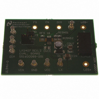
BOARD EVALUATION FOR LM3407
Manufacturer
National Semiconductor
Series
PowerWise®r
Specifications of LM3407EVAL
Current - Output / Channel
350mA
Outputs And Type
1, Non-Isolated
Voltage - Output
4.5V
Features
Dimmable
Voltage - Input
4.5 ~ 30V
Utilized Ic / Part
LM3407
Lead Free Status / RoHS Status
Contains lead / RoHS non-compliant


Inductor selection table for f
Inductor selection table for f
The LM3407 is internally compensated and requires no ex-
ternal components for feedback compensation. The compo-
nents of this evaluation board are optimized for driving 6
power LEDs with the input voltage between 22V and 30V. If
different conversions are required, such as changes to input
voltage and loading conditions, L1 and RFS may need to be
changed to ensure stable operation.
SELECTION OF INDUCTOR AND DIODE
In order to achieve accurate constant current output, the
LM3407 is required to operate in Continuous Conduction
Mode (CCM) under all operating conditions. In general, the
magnitude of the inductor ripple current should be kept as
small as possible. If the PCB size is not limited, higher induc-
tance values result in better accuracy of the output current.
However, in order to minimize the physical size of the circuit,
an inductor with minimum physical outline should be selected
such that the converter always operates in CCM and the peak
inductor current does not exceed the saturation current limit
of the inductor. The ripple and peak current of the inductor
can be calculated as follows:
TABLE 1. Suggested Inductance Value of the Inductor
VIN/V
10
15
20
25
30
10
15
20
25
30
5
5
Switching Frequency VS. R
22 µH
22 µH
22 µH
22 µH
22 µH
22 µH
22 µH
22 µH
22 µH
22 µH
22 µH
22 µH
1
(T
SW
SW
A
= 25°C)
= 500 kHz, C
= 1 MHz, C
22 µH
22 µH
33 µH
33 µH
47 µH
22 µH
22 µH
22 µH
22 µH
33 µH
2
OUT
OUT
FS
= 4.7 µF (1 µF for 1 LED)
= 4.7 µF (1 µF for 1 LED)
30046707
22 µH
22 µH
33 µH
33 µH
22 µH
22 µH
22 µH
22 µH
3
5
Number of LED
Peak to Peak Inductor Ripple Current:
Peak Inductor Current:
where n is the number of LEDs in a string and V
voltage of one LED.
The minimum inductance required for the specific application
can be calculated by:
Since the evaluation board is designed to drive a LED array
of 6 LEDs, the default value of the inductor is 33µH to ensure
CCM operation for the input voltage between 22V and 30V
with 1MHz switching frequency. For the applications with dif-
ferent input voltage or number of LEDs, the inductance of the
inductor may have to be changed to maintain accurate output
current. Table 1 shows the suggested inductance of the in-
ductor for 500kHz and 1MHz switching frequency.
The output diode of the evaluation board circuit is selected
depending on the output voltage and current. The diode must
have a rated reverse voltage higher than the input voltage of
the regulator and the peak current rating must be higher than
the expected maximum inductor current. Using a schottky
diode with low forward voltage will decrease power dissipa-
tion and increase conversion efficiency.
22 µH
22 µH
33 µH
22 µH
22 µH
22 µH
4
22 µH
22 µH
33 µH
22 µH
22 µH
22 µH
5
22 µH
22 µH
22 µH
22 µH
6
F
is the forward
www.national.com
22 µH
22 µH
7
Related parts for LM3407EVAL
Image
Part Number
Description
Manufacturer
Datasheet
Request
R

Part Number:
Description:
Precision Fahrenheit Temperature Sensors
Manufacturer:
National Semiconductor
Part Number:
Description:
National Semiconductor [8-Bit D/A Converter]
Manufacturer:
National Semiconductor
Datasheet:
Part Number:
Description:
National Semiconductor [Media Coprocessor]
Manufacturer:
National Semiconductor
Datasheet:
Part Number:
Description:
Digitally Controlled Tone and Volume Circuit with Stereo Audio Power Amplifier, Microphone Preamp Stage and National 3D Sound
Manufacturer:
National Semiconductor
Datasheet:
Part Number:
Description:
Digitally Controlled Tone and Volume Circuit with Stereo Audio Power Amplifier, Microphone Preamp Stage and National 3D Sound
Manufacturer:
National Semiconductor
Datasheet:
Part Number:
Description:
AC97 Rev 2 Codec with Sample Rate Conversion and National 3D Sound
Manufacturer:
National Semiconductor
Part Number:
Description:
Manufacturer:
National Semiconductor
Datasheet:
Part Number:
Description:
Manufacturer:
National Semiconductor
Datasheet:
Part Number:
Description:
General Purpose, Low Voltage, Low Power, Rail-to-Rail Output Operational Amplifiers
Manufacturer:
National Semiconductor
Datasheet:
Part Number:
Description:
8-bit 20 MSPS flash A/D converter.
Manufacturer:
National Semiconductor
Datasheet:
Part Number:
Description:
Low Noise Quad Operational Amplifier
Manufacturer:
National Semiconductor
Datasheet:
Part Number:
Description:
Quad Differential Line Receivers
Manufacturer:
National Semiconductor
Datasheet:
Part Number:
Description:
Quad High Speed Trapezoidal? Bus Transceiver
Manufacturer:
National Semiconductor
Datasheet:
Part Number:
Description:
Dual Line Receiver
Manufacturer:
National Semiconductor
Datasheet: