LM3445-120VFLBK/NOPB National Semiconductor, LM3445-120VFLBK/NOPB Datasheet
LM3445-120VFLBK/NOPB
Specifications of LM3445-120VFLBK/NOPB


Related parts for LM3445-120VFLBK/NOPB


LM3445-120VFLBK/NOPB Summary of contents
Page 1
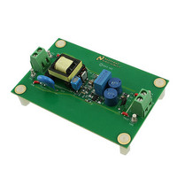
... LM3445 -120VAC, 8W Isolated Flyback LED Driver Introduction This demonstration board highlights the performance of a LM3445 based Flyback LED driver solution that can be used to power a single LED string consisting series con- nected LEDs from 135 V RMS supply. The key performance characteristics under typical operating conditions are summarized in this application note ...
Page 2
... AC power is applied, the fuse (F1) will fail open. The oscilloscope should be powered via an isolation transformer before an oscilloscope ground lead is connected to the evaluation board. Warning: The LM3445 evaluation board should not be powered with an open load. For proper operation, ensure that the desired number of LEDs are connected at the output before applying power to the evaluation board. ...
Page 3
... DIM. 3 DIM Input/output dual function dim pin. This pin can be driven with an external PWM signal to dim the LEDs. It may also be used as an output signal and connected to the DIM pin of other LM3445 or LED drivers to dim multiple LED circuits simultaneously. 4 COFF OFF time setting pin ...
Page 4
Bill of Materials Designator Description AA1 Printed Circuit Board C1 CAP .047UF 630V METAL POLYPRO C2 CAP 10000PF X7R 250VAC X2 2220 C3, C4 CAP 330UF 35V ELECT PW C5 CAP CER .33UF 250V X7R 1812 C6 CAP .10UF 305VAC ...
Page 5
... Designator Description TP2-TP5 Terminal, Turret, TH, Double TP7 TEST POINT ICT U1 Triac Dimmable Offline LED Driver, PowerWise Manufacturer Keystone Electronics - National Semiconductor 5 Part Number 1502-2 - LM3445MM www.national.com ...
Page 6
Demo Board Wiring Overview Test Point Name I/O TP3 LED + Output TP2 LED - Output TP4 LINE Input TP5 NEUTRAL Input Demo Board Assembly www.national.com Wiring Connection Diagram Description LED Constant Current Supply Supplies voltage and constant-current to anode ...
Page 7
Typical Performance Characteristics Efficiency vs. Line Voltage Original Circuit 82 8 LEDs 100 110 120 LINE VOLTAGE (V RMS ) LED Current vs. Line Voltage Original Circuit 1.0 0.8 0.7 6 LEDs 4 ...
Page 8
Output Power vs. Line Voltage Original Circuit LEDs 9 6 LEDs 100 110 LINE VOLTAGE (V RMS ) Power MOSFET Drain Voltage Waveform (V = 120V , 6 LEDs RMS FLTR2 ...
Page 9
PCB Layout Top Layer Bottom Layer 9 30115209 30115210 www.national.com ...
Page 10
Transformer Design Mfg: Wurth Electronics, Part #: 750311553 Rev. 01 www.national.com 10 30115299 30115214 ...
Page 11
Experimental Results The LED driver is designed to accurately emulate an incan- descent light bulb and therefore behave as an emulated resistor. The resistor value is determined based on the LED string configuration and the desired output power. The circuit ...
Page 12
RMS 65.5 60.5 55.2 50.6 45.7 39.4 34.2 30.3 26.0 20.0 15.2 POWER FACTOR PERFORMANCE The LED driver is able to achieve close to unity power factor (P.F. ~ 0.95) which meets Energy Star requirements. This ...
Page 13
Circuit Operation With Rotary Forward Phase Triac Dimmer The dimming operation of the circuit was verified using a for- ward phase rotary triac dimmer. Waveforms captured at dif- ferent dimmer settings are shown below: Forward phase circuit at full brightness ...
Page 14
Electromagnetic Interference (EMI) The EMI input filter of this evaluation board is configured as shown in the following circuit diagram. In order to get a quick estimate of the EMI filter performance, only the PEAK conductive EMI scan was measured ...
Page 15
Thermal Analysis The board temperature was measured using an IR camera (HIS-3000, Wahl) while running under the following condi- tions 120 V IN RMS I = 365 mA LED # of LEDs = 7.3 W ...
Page 16
... INJECTING LINE VOLTAGE INTO FILTER-2 (achieving PFC > 0.95 small portion (750mV to 1.00V) of line voltage is injected at FLTR2 of the LM3445, the circuit is essentially turned into a constant power flyback as shown in Figure 6. FIGURE 6. Line Voltage Injection Circuit The LM3445 works as a constant off-time controller normally, but by injecting the 1 ...
Page 17
Notes 17 www.national.com ...
Page 18
... For more National Semiconductor product information and proven design tools, visit the following Web sites at: www.national.com Products Amplifiers www.national.com/amplifiers Audio www.national.com/audio Clock and Timing www.national.com/timing Data Converters www.national.com/adc Interface www.national.com/interface LVDS www.national.com/lvds Power Management www.national.com/power Switching Regulators www.national.com/switchers LDOs www.national.com/ldo LED Lighting www ...