LM2754SQEV National Semiconductor, LM2754SQEV Datasheet - Page 2
LM2754SQEV
Manufacturer Part Number
LM2754SQEV
Description
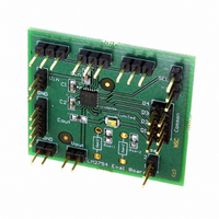
BOARD EVALUATION LM2754SQ
Manufacturer
National Semiconductor
Series
PowerWise®r
Specifications of LM2754SQEV
Current - Output / Channel
800mA
Outputs And Type
4, Non-Isolated
Voltage - Output
5.1V
Features
Charge Pump
Voltage - Input
2.7 ~ 5.5V
Utilized Ic / Part
LM2754
Core Chip
LM2754
Topology
Charge Pump
No. Of Outputs
1
Output Current
800mA
Input Voltage
2.8V To 5.5V
Kit Contents
Board
Development Tool Type
Hardware - Eval/Demo Board
Lead Free Status / RoHS Status
Not applicable / Not applicable


www.national.com
Connection Diagram
Pin Descriptions
Ordering Information
12, 13, 14, 15
Order Number
1, 2, 7, 5
9, 16, 17
LM2754SQX
LM2754SQ
10, 11
23,24
4, 6
Pin
22
21
20
19
18
8
3
Note: EN, T/F, TX, and SEL pins each have a 500kΩ resistor connected internally to GND
C
D1, D2, D3, D4*
1
+, C
No Connect
I
SET1
GND
Name
V
V
GND
1
SEL
T/F
INSW
V
EN
-, C
TX
OUT
, I
IN
Package Description
24-pin No-Pullback Leadless Leadframe Package (LLP-24)
SW
SET2
2
+, C
No-Pullback
2
LLP-24
- Flying Capacitor Connections.
Input Voltage Connection for Switch Array. Pins 23 and 24 are connected
internally on the die. Connect V
Input Voltage Connection. Connect V
Output Voltage. Connect to LED Anodes.
Regulated Current Sink Inputs. (* See SEL PIN description)
Switch Array Ground Connection. Connect GND and GND
Ground Connection. Connect GND and GND
Enable Control Pin. Logic High = Normal Operation in Torch Mode.
Logic Low = Device Shut-Down. (See Note)
Torch/Flash Control Pin. Logic High = Flash Mode. Logic Low = Torch Mode.
Device must be enabled for Torch or Flash to operate. (See Note)
Current Set Resistor Connections. Connect 1% resistors to ground to set the
desired current through the LEDs. LED current is approximated by the
equation: 800 x (1.25V ÷ R). This equation corresponds to the current through
one current sink. Total LED current is equal to the sum of currents through all
current sinks connected to the LED. The equation used for Torch (I
Flash (I
RF PA synchronization control pin. Logic High = Force Torch Mode. Logic Low
= Normal Operation. (See Applications Information section for the full
operational description) (See Note)
D
D
Do not connect to any node.
4
4
Control Pin. Logic Low = Normal 4-LED Operation. Logic High = Disable
LED Input. Connect D
NS Package Number SQA24A
SET2
4mm x 4mm x 0.8mm
) resistors are the same.
LM2754
2
Package Marking
4
to V
UZXYTT
LM2754
OUT
IN
Description
and V
when not used. (See Note)
IN
and V
INSW
SW
pins together.
INSW
pins together.
Supplied as Tape and Reel
pins together.
SW
(Units)
20202802
1000
4500
pins together.
SET1
) and
Related parts for LM2754SQEV
Image
Part Number
Description
Manufacturer
Datasheet
Request
R

Part Number:
Description:
Accurate, 120 C-150 C Factory Preset Thermostat Lm27 Form
Manufacturer:
National Semiconductor Corporation
Datasheet:

Part Number:
Description:
Factory Preset Thermostat
Manufacturer:
National Semiconductor
Datasheet:
Part Number:
Description:
National Semiconductor [8-Bit D/A Converter]
Manufacturer:
National Semiconductor
Datasheet:
Part Number:
Description:
National Semiconductor [Media Coprocessor]
Manufacturer:
National Semiconductor
Datasheet:
Part Number:
Description:
Digitally Controlled Tone and Volume Circuit with Stereo Audio Power Amplifier, Microphone Preamp Stage and National 3D Sound
Manufacturer:
National Semiconductor
Datasheet:
Part Number:
Description:
Digitally Controlled Tone and Volume Circuit with Stereo Audio Power Amplifier, Microphone Preamp Stage and National 3D Sound
Manufacturer:
National Semiconductor
Datasheet:
Part Number:
Description:
AC97 Rev 2 Codec with Sample Rate Conversion and National 3D Sound
Manufacturer:
National Semiconductor
Part Number:
Description:
Manufacturer:
National Semiconductor
Datasheet:
Part Number:
Description:
Manufacturer:
National Semiconductor
Datasheet:
Part Number:
Description:
General Purpose, Low Voltage, Low Power, Rail-to-Rail Output Operational Amplifiers
Manufacturer:
National Semiconductor
Datasheet:
Part Number:
Description:
8-bit 20 MSPS flash A/D converter.
Manufacturer:
National Semiconductor
Datasheet:
Part Number:
Description:
Low Noise Quad Operational Amplifier
Manufacturer:
National Semiconductor
Datasheet:
Part Number:
Description:
Quad Differential Line Receivers
Manufacturer:
National Semiconductor
Datasheet:
Part Number:
Description:
Quad High Speed Trapezoidal? Bus Transceiver
Manufacturer:
National Semiconductor
Datasheet: