NCP1351LEDGEVB ON Semiconductor, NCP1351LEDGEVB Datasheet - Page 3
NCP1351LEDGEVB
Manufacturer Part Number
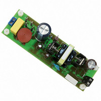
NCP1351LEDGEVB
Description
EVAL BOARD FOR NCP1351LEDG
Manufacturer
ON Semiconductor
Datasheets
1.NCP1351APG.pdf
(27 pages)
2.NCP1351LEDGEVB.pdf
(11 pages)
3.NCP1351LEDGEVB.pdf
(3 pages)
Specifications of NCP1351LEDGEVB
Design Resources
NCP1351 EVB BOM NCP1351LEDGEVB Gerber Files NCP1351LED EVB Schematic
Current - Output / Channel
700mA
Outputs And Type
1, Isolated
Voltage - Output
33V
Features
Short-Circuit Protection
Voltage - Input
85 ~ 265 V
Utilized Ic / Part
NCP1351
Core Chip
NCP1351
Topology
Flyback
No. Of Outputs
1
Output Current
700mA
Output Voltage
33V
Development Tool Type
Hardware - Eval/Demo Board
Leaded Process Compatible
Yes
Rohs Compliant
Yes
Lead Free Status / RoHS Status
Lead free / RoHS Compliant
For Use With/related Products
NCP1351LEDG
Other names
NCP1351LEDGEVBOS


LED Current
current so the control loop will be constant current, with a
simple Zener to limit the maximum output voltage.
are the nominal forward voltage characteristics of the
LUXEON
power of 20.2 W at 28.8 V.
Inductor selection
transformer primary is dependant on the mode of
operation and the output power. Discontinuous operation
requires lower inductance but results in higher peak to
average current waveforms, and thus higher losses. For
low power designs, such as this ballast, the inductance is
designed to be just continuous (or just discontinuous)
under worst case conditions, that is minimum line and
maximum load.
there will be some sag on the DC bulk capacitors so an
allowance will be made for this by using 80 V as the
minimum input voltage, including MOSFET drop etc.
the MOSFET drain rating, line voltage and reflected
secondary voltage. Since this is a constant current circuit
we are designing, with a varying output voltage, we need
the maximum output voltage.
maximum allowable drain voltage is:
voltage and leakage spike of:
September 2008, Rev. 2
The light output of an LED is determined by the forward
Typical forward voltages vary by LED supplier, below
Driving eight LED’s at 700mA thus gives an output
In a flyback converter the inductance required in the
The specification for this ballast is as follows:
• Universal input – 85 Vac to 265 Vac
• 25 W maximum input power – PFC limit
• Assuming 80% efficiency – 20 W output power
• 700 mA output current
• 100 kHz operation at full load
This gives us a minimum DC input voltage of 120 V,
First we need to calculate the turn’s ratio, this is set by
With a 600 V MOSFET and derating of 80%, our
And thus headroom, V
V
V
CLAMP
D
(
V
V
V
margin for safety).
max
IN(max)
IN(min)
OUT
1000 mA
1500 mA
®
350 mA
700 mA
)
K2 at different operating currents.
=
=
=
I
F
is 35 V (20 W @ 700 mA is 29 V plus a
V
105
600
is the minimum rectified input = 80 V.
is the maximum rectified input = 375 V.
D
(
max
V
×
)
0
−
8 .
3.42 V
3.60 V
3.72 V
3.85 V
V
IN
V
=
F
CLAMP
(
480
max
)
=
V
for the reflected secondary
480
..........................(Eq.3)
−
375
..........(Eq.4)
DN06040/D
www.onsemi.com
once the voltage drop across this reaches the base-
emitter threshold of the PNP transistor current flows in the
opto-coupler diode and thus in the FB pin of the NCP1351.
of dissipating 420 mW, two 330 mW surface mount
resistors, 1.8 Ω each in parallel, are used.
the reflected secondary:
transformer construction.
in CCM:
The output current is sensed by a series resistance,
The LED current is thus set by:
Total sense resistor power dissipation is:
So for 700 mA we need a 0.9 Ω sense resistor capable
Good results are obtained if we set V
Re-arranging for N:
We will use a ratio of 0.5 or 2:1, this will give a good
We can now calculate the maximum duty cycle running
δ
I
P
k
N
.......................................................................... (Eq.7)
LED
C
D
MAX
=
=
=
=
V
=
f
. 0
N
N
I
(
V
= 0.7 V as we will need a high voltage diode.
=
=
V
LED
51
R
CLAMP
P
S
0
OUT
V
. 0
SENSE
6 .
=
OUT
47
×
V
1
+
0
5 .
×
6 .
+
V
V
×
.................................................. (Eq.1)
V
N
OUT
V
f
(
IN
)
105
35
............................................. (Eq.2)
=
(
min
1
+
5 .
)
0
N
7 .
................................... (Eq.5)
=
)
.............................. (Eq.6)
(
35
+
(
0
35
7 .
CLAMP
+
)
+
0
7 .
80
, at ~150% of
)
×
0
5 .
3
Related parts for NCP1351LEDGEVB
Image
Part Number
Description
Manufacturer
Datasheet
Request
R

Part Number:
Description:
ON Semiconductor [VOLTAGE REGULATOR]
Manufacturer:
ON Semiconductor
Datasheet:
Part Number:
Description:
357-036-542-201 CARDEDGE 36POS DL .156 BLK LOPRO
Manufacturer:
ON Semiconductor
Datasheet:
Part Number:
Description:
357-036-542-201 CARDEDGE 36POS DL .156 BLK LOPRO
Manufacturer:
ON Semiconductor
Datasheet:
Part Number:
Description:
357-036-542-201 CARDEDGE 36POS DL .156 BLK LOPRO
Manufacturer:
ON Semiconductor
Datasheet:
Part Number:
Description:
357-036-542-201 CARDEDGE 36POS DL .156 BLK LOPRO
Manufacturer:
ON Semiconductor
Datasheet:
Part Number:
Description:
357-036-542-201 CARDEDGE 36POS DL .156 BLK LOPRO
Manufacturer:
ON Semiconductor
Datasheet:
Part Number:
Description:
357-036-542-201 CARDEDGE 36POS DL .156 BLK LOPRO
Manufacturer:
ON Semiconductor
Datasheet:
Part Number:
Description:
357-036-542-201 CARDEDGE 36POS DL .156 BLK LOPRO
Manufacturer:
ON Semiconductor
Datasheet:
Part Number:
Description:
357-036-542-201 CARDEDGE 36POS DL .156 BLK LOPRO
Manufacturer:
ON Semiconductor
Datasheet:
Part Number:
Description:
357-036-542-201 CARDEDGE 36POS DL .156 BLK LOPRO
Manufacturer:
ON Semiconductor
Datasheet:
Part Number:
Description:
357-036-542-201 CARDEDGE 36POS DL .156 BLK LOPRO
Manufacturer:
ON Semiconductor
Datasheet:
Part Number:
Description:
Manufacturer:
ON Semiconductor
Datasheet:
Part Number:
Description:
Manufacturer:
ON Semiconductor
Datasheet:
Part Number:
Description:
Manufacturer:
ON Semiconductor
Datasheet: