MCP1252DM-BKLT Microchip Technology, MCP1252DM-BKLT Datasheet - Page 12
MCP1252DM-BKLT
Manufacturer Part Number
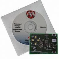
MCP1252DM-BKLT
Description
BOARD DEMO FOR MCP1252
Manufacturer
Microchip Technology
Specifications of MCP1252DM-BKLT
Current - Output / Channel
120mA
Outputs And Type
1, Non-Isolated
Features
Short-Circuit and Thermal Protection, Shutdown
Voltage - Input
2 ~ 5.5V
Utilized Ic / Part
MCP1252
Processor To Be Evaluated
MCP1252
Lead Free Status / RoHS Status
Contains lead / RoHS non-compliant
Voltage - Output
-
Lead Free Status / Rohs Status
Lead free / RoHS Compliant


MCP1252 Charge Pump Backlight LED Demo Board User’s Guide
2.3
DS51551A-page 8
GETTING STARTED
The MCP1252 Charge Pump Backlight LED Demo Board comes fully assembled and
tested. The board requires 3 AAA batteries as a power source for the application.
2.3.1
Insert three AAA batteries into the battery pack on the bottom of the board. As soon as
the system powers up, the internal program of the PIC10F206 will initialize and remain
in a low-power sleep mode (<1 µA) until the S1 button is pressed by the user.
The MCP1252 Charge Pump Backlight LED Demo Board does not need a power
switch or power jumper because of the “standby” or “sleep” mode of the PIC10F206
microcontroller. Upon entering Sleep mode, the system requires less than 1 µA (typ) of
current. So, with three AAA batteries used in the application (at 1250 mAh per battery),
the system’s power requirements in Sleep mode are minimal (the “shelf life” of an alka-
line battery is 5-7 years, whereas the system current load in Sleep mode would
discharge the battery pack in about 400 years!).
FIGURE 2-1:
Powering the MCP1252 Charge Pump Backlight LED Demo
Board
Setup Configuration Diagram.
© 2005 Microchip Technology Inc.
“Power On/Off”
Push Button
Switch
“Power On/Off”
Push Button
Switch
Related parts for MCP1252DM-BKLT
Image
Part Number
Description
Manufacturer
Datasheet
Request
R

Part Number:
Description:
Manufacturer:
Microchip Technology Inc.
Datasheet:
Part Number:
Description:
Manufacturer:
Microchip Technology Inc.
Datasheet:
Part Number:
Description:
Manufacturer:
Microchip Technology Inc.
Datasheet:
Part Number:
Description:
Manufacturer:
Microchip Technology Inc.
Datasheet:
Part Number:
Description:
Manufacturer:
Microchip Technology Inc.
Datasheet:
Part Number:
Description:
Manufacturer:
Microchip Technology Inc.
Datasheet:
Part Number:
Description:
Manufacturer:
Microchip Technology Inc.
Datasheet:
Part Number:
Description:
Manufacturer:
Microchip Technology Inc.
Datasheet: