LM3405XEVAL National Semiconductor, LM3405XEVAL Datasheet

BOARD EVALUATION LM3405X

LM3405XEVAL

Manufacturer Part Number
LM3405XEVAL
Description
BOARD EVALUATION LM3405X
Manufacturer
National Semiconductor
Series
PowerWise®r
Datasheets

Specifications of LM3405XEVAL

Current - Output / Channel
1A
Outputs And Type
1, Non-Isolated
Voltage - Output
0.2 ~ 13.5 V
Features
Dimmable
Voltage - Input
3 ~ 15V
Utilized Ic / Part
LM3405
Kit Contents
Board, Datasheet
Svhc
No SVHC (15-Dec-2010)
Kit Features
Cycle-by-Cycle Current Limit,
Rohs Compliant
No
Lead Free Status / RoHS Status
Contains lead / RoHS non-compliant
© 2007 National Semiconductor Corporation
LM3405 Demo Board
Introduction
The LM3405 demo board is configured to drive a series string
of high power, high brightness LEDs at a forward current of
1A using the LM3405 constant current buck regulator. The
board can accept a full input operating range of 3V to 15V.
The converter output voltage adjusts as needed to maintain
a constant current through the LED array. The LM3405 is a
step-down regulator with an output voltage range extending
from a V
determined by the maximum duty cycle (typically 94%). It can
drive up to 3 LEDs in series at 1A forward current, with the
single LED forward voltage of approximately 3.7V (Typical of
white, blue, and green LEDs using InGaN technology).
As shown in the demo board schematic circuit in Figure 1, the
board is configured with the boost voltage derived from V
through a shunt zener (D3). This will ensure that the gate drive
voltage V
to 5.5V when V
voltages (3V to 5V) being used, the boost diode (D2) can be
directly connected to V
to obtain sufficient gate drive voltage for best performance.
Table 1 lists the bill of materials of this demo board. The mea-
sured performance characteristics and layout of this board
are also included below. Additional Circuit Configuration
Schematics section illustrates other possible circuit configu-
rations of this board to accommodate various input and output
requirements as discussed in the LM3405 datasheet.
Connecting to LED Array
The LM3405 Demo Board includes a female 6-position SIP
connector P1 as well as two standard 72mil turret connectors
O(MIN)
BOOST
of 205mV (the reference voltage) to a V
IN
- V
varies from 5V to 15V. In cases of low input
SW
falls in the recommended range of 2.5V
IN
(R3 short, C4 and D3 not installed)
FIGURE 1. LM3405 Demo Board Schematic
300100
O(MAX)
IN
National Semiconductor
Application Note 1590
Alex Gao
March 2007
for the cathode and anode connections of the LED array. Solid
18 or 20 gauge wire with about 1cm of insulation stripped
away makes a convenient, solderless connection to P1.
Setting the LED Current
The default forward current I
1.0A. To adjust this value the current setting resistor R1 can
be changed according to the following equation:
The feedback voltage V
The resistor R1 should be rated to handle the power dissipa-
tion of the LED current. R1 should be less than approximately
1Ω, to ensure that the LED current is kept above 200mA. If
average LED currents of less than 200mA are desired, the
EN/DIM pin should be used for PWM dimming.
PWM Dimming
The default connection of the PWM terminal is tied to V
through a 100kΩ resistor (R2) to enable the chip, which allows
the set current to flow through the LEDs continuously. This
PWM terminal can also be connected separately to a periodic
pulse signal at different frequencies and/or duty cycle for
PWM dimming. A typical LED current waveform in PWM dim-
ming mode is shown in Figure 2. Figure 3 shows the average
LED current versus duty cycle of PWM dimming signal for
various frequencies. Due to an approximately 100µs delay
between the dimming signal and LED current, the dimming
ratio reduces dramatically if the applied PWM dimming fre-
quency is greater than 5kHz.
I
F
FB
= V
is regulated at 0.205V typically.
F
FB
delivered to the LED array is
/ R1
www.national.com
30010001
IN

Related parts for LM3405XEVAL

LM3405XEVAL Summary of contents

Page 1

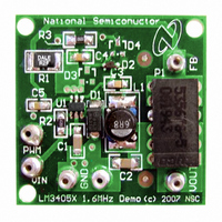
... LM3405 datasheet. Connecting to LED Array The LM3405 Demo Board includes a female 6-position SIP connector P1 as well as two standard 72mil turret connectors © 2007 National Semiconductor Corporation National Semiconductor Application Note 1590 Alex Gao March 2007 for the cathode and anode connections of the LED array ...

Page 2

... Part Value SLF6028T-6R8M1R5-PF GRM31CR61E106KA12L C1206C105K3RACTU 0805YC103KAT2A GRM219R71C104KA01D GRM216R61E105KA12D Not installed WSL2010R2000FEA CRCW0805100KFKEA CRCW08051K00FKEA 2 PWM Dimming Signal at PWM Terminal Part Number Manufacturer LM3405 National Semiconductor TDK Murata Kemet AVX Murata Murata MBRA130LT3G ON Semiconductor BAT54WS-TP Micro Commercial Co. BZX84C5V1 Fairchild Semiconductor Vishay Vishay Vishay ...

Page 3

Typical Performance Characteristics Efficiency vs LED Current (V = 5V, V Derived from V IN BOOST Efficiency vs Input Voltage (I Startup during PWM Dimming (V = 12V 1A Efficiency vs LED Current ( ...

Page 4

Layout www.national.com Top Layer and Top Overlay Bottom Layer and Bottom Overlay 4 30010010 30010011 ...

Page 5

Internal Plane 1 (GND) Internal Plane 30010012 30010013 www.national.com ...

Page 6

Additional Circuit Configuration Schematics www.national.com V Derived from V BOOST IN V Derived from V BOOST OUT 6 30010014 30010015 ...

Page 7

V Derived from V through a Series Zener Diode BOOST IN V Derived from V through a Series Zener Diode BOOST OUT 7 30010016 30010017 www.national.com ...

Page 8

... National Semiconductor and the National Semiconductor logo are registered trademarks of National Semiconductor Corporation. All other brand or product names may be trademarks or registered trademarks of their respective holders. ...

Related keywords